
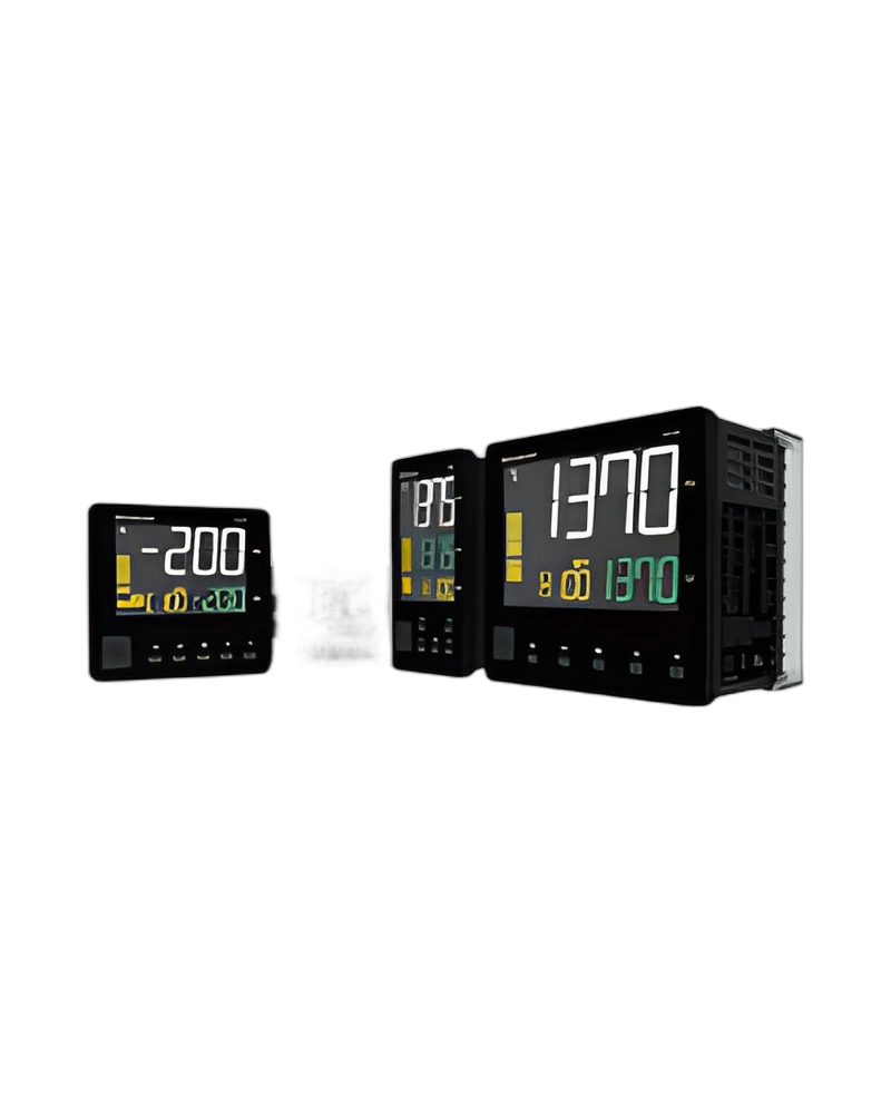
Explore performance details, construction highlights, applications, and technical information in one clear overview.
VX series high-performance LCD temperature controller is a Hanyoung NUX temperature controller for monitoring and regulating process temperature. The available configuration is built around the listed sensor inputs, control method and output arrangement, with model information of VX series high-performance LCD temperature controller. Control output: Relay output | ▪Rated switching capacity : 5 A 240 V a.c., 5 A 30 V d.c. ▪Max. switching power : 750 VA, 90 W ▪Max. switching voltage : 240 V a.c., 110 V d.c. ▪Max. switching current : 5 A ▪Mechanical life : 20 million times (at 180 CPM); AC voltage type voltage pulse output: 12 V d.c. ± 1 V d.c. pulse voltage (load resistance min. 600 Ω); DC voltage type voltage pulse output: 12 - 15 V d.c. pulse voltage (load resistance min. 600 Ω); Current output: 4~20 mA ± 0.2 % of FS ± 1 digit, load resistance : max. 600 Ω.
For panel and process selection, the important characteristics are the input sensor type, control response, power requirements and display or communication options. Display part (H*W) mm: Display method | Wide viewing angle LCD; Protocol: ▪Protocol : PC-LINK ▪Baudrate : 38400 bps ▪Start bit : 1 bit ▪Data bit : 8 bit ▪Parity bit : None ▪Stop bit : 1 bit; Protocol: ▪PC-LINK STD ▪PC-LINK WITH SUM ▪MODBUS-ASCII ▪MODBUS-RTU ▪MC Protocol(format4) ▪XGT Cnet Server Mode; Communication: C | RS-485 communication.
Key strengths of the VX series high-performance LCD temperature controller come from the combination of its functional configuration and practical installation specifications. The following characteristics highlight the values that matter most when comparing the product with equipment requirements.
Input: Thermo couple | K, J, E, T, R, B, S, L, N, U, W, PLII; Control output: Relay output | ▪Rated switching capacity : 5 A 240 V a.c., 5 A 30 V d.c. ▪Max. switching power : 750 VA, 90 W ▪Max. switching voltage : 240 V a.c., 110 V d.c. ▪Max. switching current : 5 A ▪Mechanical life : 20 million times (at 180 CPM); DC Power Supply Voltage: 24 V d.c., Class2; Sampling cycle: 50 ms; Display part (H*W) mm: Display method | Wide viewing angle LCD.
The VX series high-performance LCD temperature controller is specified by its sensor input, control output, electrical supply, sampling behaviour and accuracy. These values determine how the controller measures temperature and applies its selected control response. Output operation: Reverse action, direct action; Retrans mission output: ▪1 output ▪4 ~ 20 mA ± 0.2 % of FS ± 1 digit ▪load resistance : max. 600 Ω; OUT 1 (control output 1): M | Relay output; OUT 2 (control output 2): N | None.
Additional technical characteristics include Sub output: A1 | 1 relay output (VX4 basic option); Retransmission output (RET): T | Retransmission output (4 ~ 20 mA); ▪Relay 1 ~ 4 outputs ▪rated switching capacity: 5A 240 V a.c., 5 A 30 V d.c..
The physical design of VX series high-performance LCD temperature controller should be considered together with the installation environment and the available mounting or display arrangement. Weight: 202 g | 202 g | 120 g | 194 g | 290 g; Size: 2 | 48(W) x 96(H) x 62.5(D) ㎜; Product dimensions: W | 48.0 | 96.0 | 48.0 | 72.0 | 96.0; Panel cutout: H1 *1) | 45.0 | 90.5 | 45.0 | 67.5 | 92.0.
Further construction and environmental details include Insulation resistance: Min. 20 MΩ, 500 V d.c.; Dielectric strength: ▪3,000 V a.c. ▪50/60 Hz for 1 minute (between 1st and 2nd terminal); Ambient temperature & humidity: -10 ~ 50 ℃, 35 ~ 85 % RH (without condensation).
Integration of VX series high-performance LCD temperature controller requires the correct sensor input, control output, supply voltage and configuration settings for the application. ▪Protocol: PC-LINK ▪Baudrate : 38400 bps ▪Start bit : 1 bit; DC Power Supply Voltage: 24 V d.c., Class2; AC voltage type power consumption: Max. 8.5 VA | Max. 8.5 VA | Max. 8.2 VA | Max. 8.5 VA | Max. 9.0 VA; DC voltage type power consumption: Max. 2.7 W | Max. 2.7 W | Max. 2 W | Max. 2.8 W | Max. 3.2 W.
Additional operating and interface details include Reference junction compen sation accuracy: ± 1.5 ℃ (within -10 ~ 50 ℃); Sampling cycle: 50 ms. These values provide a practical reference for wiring, setup and normal operation within the selected configuration.
Choose VX series high-performance LCD temperature controller by confirming the exact model or configuration against the required operating conditions. The available model information is VX series high-performance LCD temperature controller. Option: Sub output | ▪Relay 1 ~ 4 outputs ▪rated switching capacity : 5A 240 V a.c., 5 A 30 V d.c.; Model: Code | Content; Storage temperature: -25 ~ 65 ℃; Input: Thermo couple | K, J, E, T, R, B, S, L, N, U, W, PLII.
Before installation, confirm Control output: Relay output | ▪Rated switching capacity : 5 A 240 V a.c., 5 A 30 V d.c. ▪Max. switching power : 750 VA, 90 W ▪Max. switching voltage : 240 V a.c., 110 V d.c. ▪Max. switching current : 5 A ▪Mechanical life : 20 million times (at 180 CPM); DC Power Supply Voltage: 24 V d.c., Class2; Sampling cycle: 50 ms. Matching the model, electrical ratings, signal requirements, physical arrangement and environmental limits helps keep the product within its specified operating conditions.
| Specification | Details |
|---|---|
| Classification | VX2 | VX3 | VX4 | VX7 | VX9 |
| Input | Thermo couple | K, J, E, T, R, B, S, L, N, U, W, PLII |
| Reference junction compen sation accuracy | ± 1.5 ℃ (within -10 ~ 50 ℃) |
| RTD | JPT100, PT100 |
| Allowable line resistance | Each 3 wire within 10 Ω (but the resistance among 3 lines should be same) |
| DC voltage / current | 1 ~ 5 V (4 ~ 20 mA), 0 ~ 5 V, 0 ~ 10 V, 0 ~ 50 mV, 0 ~ 100 mV |
| Sampling cycle | 50 ms |
| Control output | Relay output | ▪Rated switching capacity : 5 A 240 V a.c., 5 A 30 V d.c. ▪Max. switching power : 750 VA, 90 W ▪Max. switching voltage : 240 V a.c., 110 V d.c. ▪Max. switching current : 5 A ▪Mechanical life : 20 million times (at 180 CPM) |
| AC voltage type voltage pulse output | 12 V d.c. ± 1 V d.c. pulse voltage (load resistance min. 600 Ω) |
| DC voltage type voltage pulse output | 12 - 15 V d.c. pulse voltage (load resistance min. 600 Ω) |
| Current output | 4~20 mA ± 0.2 % of FS ± 1 digit, load resistance : max. 600 Ω |
| Control | Control type | ON/OFF, PID control, 2DOF PID control |
| Output operation | Reverse action, direct action |
| Memory | Non-volatile memory life | ▪EEPROM unlocked : when setting E2P.L : OFF in G.SET group (EEPROM life : 1 million times write guaranteed) ▪EEPROM locked : when setting E2P.L : ON in G.SET group (store in RAM) |
| Display part (H*W) mm | Display method | Wide viewing angle LCD |
| PV character | 20.5 x 6.9 | 19.7 x 7.2 | 15.2 x 6.8 | 19.8 x 9.3 | 29.0 x 13.6 |
| SV character | 12.8 x 5.9 | 10.7 x 4.7 | 7.4 x 3.9 | 10.2 x 4.9 | 15.0 x 7.2 |
| MV character | 9.3 x 4.4 | 7.3 x 3.5 | 7.4 x 3.9 | 7.5 x 3.3 | 11.0 x 4.8 |
| USB Loader | Communi cation method | USB 2.0 |
| Protocol | ▪Protocol : PC-LINK ▪Baudrate : 38400 bps ▪Start bit : 1 bit ▪Data bit : 8 bit ▪Parity bit : None ▪Stop bit : 1 bit |
| Communi cation distance | Within 5 m |
| Option | Sub output | ▪Relay 1 ~ 4 outputs ▪rated switching capacity : 5A 240 V a.c., 5 A 30 V d.c. |
| Digital input | ▪2 points or 4 point (Digital Input (DI) 4 points can be selected as default for VX2, VX3, VX9, and conditionally for VX4/VX7.) ▪Contact input ON : 1 KΩ max., OFF: 100 KΩ min. ▪Non-contact input ON : 1.5 V max., OFF: 0.1 mA max. ▪Current Flow : approx. 2 mA per contact, ▪Voltage at open : Approx. 5 V d.c. |
| Retrans mission output | ▪1 output ▪4 ~ 20 mA ± 0.2 % of FS ± 1 digit ▪load resistance : max. 600 Ω |
| Remote input | ▪1 input ▪4 ~ 20 mA (1 ~ 5 V) |
| Current detection input | ▪1 input or 2 inputs ▪0.0 - 50.0 A ▪CT-70 current transformer (sold separately) (Detection Input (CT) 2 points can be selected as default for VX2, VX3, VX9, and conditionally for VX4/VX7.) |
| RS-485 | Commu nic method | ▪EIA RS485 standard ▪2-wire half-duplex |
| Max. connec tions | 31 (address setting 1~99 available) |
| Commu nic sequence | No sequence |
| Commu nic distance | Within 1.2 ㎞ |
| Commu nic speed | 4800, 9600, 14400, 19200, 38400, 57600 bps |
| bit | ▪Start bit : 1 bit ▪Data bit : 7 or 8 bit ▪Parity bit : NONE / EVEN / ODD ▪Stop bit : 1 or 2 bit |
| Protocol | ▪PC-LINK STD ▪PC-LINK WITH SUM ▪MODBUS-ASCII ▪MODBUS-RTU ▪MC Protocol(format4) ▪XGT Cnet Server Mode |
| Respon se time | Actual response time = processing time + (response time X 50 ms) |
| Power | AC Power Supply Voltage | 100 - 240 V a.c., 50/60 Hz |
| DC Power Supply Voltage | 24 V d.c., Class2 |
| Voltage fluc tuation rate | ± 10 % of power voltage |
| Insulation resistance | Min. 20 MΩ, 500 V d.c. |
| Dielectric strength | ▪3,000 V a.c. ▪50/60 Hz for 1 minute (between 1st and 2nd terminal) |
| AC voltage type power consumption | Max. 8.5 VA | Max. 8.5 VA | Max. 8.2 VA | Max. 8.5 VA | Max. 9.0 VA |
| DC voltage type power consumption | Max. 2.7 W | Max. 2.7 W | Max. 2 W | Max. 2.8 W | Max. 3.2 W |
| Ambient temperature & humidity | -10 ~ 50 ℃, 35 ~ 85 % RH (without condensation) |
| Storage temperature | -25 ~ 65 ℃ |
| IP65 (front panel) | IP65 (front panel) | IP66 (front panel) | IP65 (front panel) | IP65 (front panel) |
| Weight | 202 g | 202 g | 120 g | 194 g | 290 g |
| Basic components | Main body, Bracket, 250 Ω resistor (1%) , Rubber packing, Instruction manual |
| Model | Code | Content |
| VX | - | - | LCD Digital Temperature Controller |
| Size | 2 | 48(W) x 96(H) x 62.5(D) ㎜ |
| 3 | 96(W) x 48(H) x 62.5(D) ㎜ |
| 4 | 48(W) x 48(H) x 63(D) ㎜ |
| 7 | 72(W) x 72(H) x 62.5(D) ㎜ |
| 9 | 96(W) x 96(H) x 62.5(D) ㎜ |
| Sensor | U | Universal input |
| OUT 1 (control output 1) | M | Relay output |
| S | Voltage pulse output (voltage pulse output for SSR drive) |
| C | Current output (4-20 mA current output for SCR drive) |
| OUT 2 (control output 2) | N | None |
| M | Relay output |
| Power | A | 100 - 240 V a.c., 50/60 Hz |
| D | 24 V d.c., Class2 |
| Sub output | A1 | 1 relay output (VX4 basic option) |
| A2 | 2 relay outputs (VX2, VX7, VX9 basic option) |
| A4 | 4 relay outputs (※ *1) |
| Communication | C | RS-485 communication |
| Retransmission output (RET) | T | Retransmission output (4 ~ 20 mA) |
| Digital input (DI) | D2 | 2 digital inputs (DI 1 ~ 2) |
| D4 | 4 digital inputs (DI 1 ~ 4) (※ *2) |
| Current detection input (CT) | H1 | Current detection input (CT) 1 contact |
| H2 | Current detection input (CT) 2 contact (※ *3) |
| Remote input (REM) | R | 1 input, 4 ~ 20 mA (1 ~ 5 V) |
| Classification | Type | VX2 | VX3 | VX4 | VX7 | VX9 |
| Product dimensions | W | 48.0 | 96.0 | 48.0 | 72.0 | 96.0 |
| H | 96.0 | 48.0 | 48.0 | 72.0 | 96.0 |
| D | 62.5 | 62.5 | 63.0 | 62.5 | 62.5 |
| D1 | 5.5 | 5.5 | 5.0 | 5.5 | 5.5 |
| L | 78.4 | 78.4 | 78.4 | 78.4 | 78.4 |
| Panel cutout | H1 *1) | 45.0 | 90.5 | 45.0 | 67.5 | 92.0 |
| H1 *1) | 90.5 | 45.0 | 45.0 | 67.5 | 92.0 |
| A | 70.0 | 122.0 | 60.0 | 83.0 | 117.0 |
| B *2) | 122.0 | 70.0 | 60.0 | 100.0 | 117.0 |
| Classification | Type | TC2A -COV | TC4A -COV | TC7A -COV | TC9A -COV |
| Protective cover | W2 | 48.4 | 94.4 | 48.0 | 71.8 | 96.0 |
| H2 | 94.4 | 48.4 | 48.1 | 71.8 | 96.0 |
| D2 | 26.9 | 26.9 | 24.0 | 26.9 | 26.9 |
| ▪Rated switching capacity | 5 A 240 V a.c., 5 A 30 V d.c. ▪Max. switching power : 750 VA, 90 W |
| ▪Max. switching voltage | 240 V a.c., 110 V d.c. ▪Max. switching current : 5 A |
| 4~20 mA ± 0.2 % of FS ± 1 digit, load resistance | max. 600 Ω |
| ▪Protocol | PC-LINK ▪Baudrate : 38400 bps ▪Start bit : 1 bit |
| ▪Relay 1 ~ 4 outputs ▪rated switching capacity | 5A 240 V a.c., 5 A 30 V d.c. |
| ▪Contact input ON | 1 KΩ max., OFF: 100 KΩ min. |
| ▪Non-contact input ON | 1.5 V max., OFF: 0.1 mA max. |
| ▪Current Flow | approx. 2 mA per contact, |
| ▪Voltage at open | Approx. 5 V d.c. |
| ▪load resistance | max. 600 Ω |
Browse product families and jump into the exact catalog section you need.