
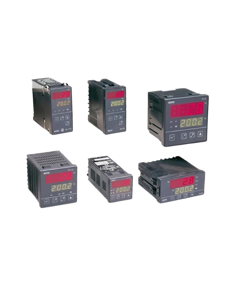
Explore performance details, construction highlights, applications, and technical information in one clear overview.
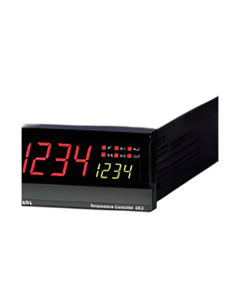
MT Series PID Temperature Controller is a Hanyoung NUX temperature controller for monitoring and regulating process temperature. The available configuration is built around the listed sensor inputs, control method and output arrangement, with model information of Code | Function. Allowable signal source resistance: T/C: Max 250 Ω, DC mV/V: Less than 2 kΩ; Allowable input voltage: DC mV/Thermocouple/RTD: ±10 V, DC V: ±20 V; Input signal break detection (Burn - out): T/C: Up Scale / Down Scale RTD: Up Scale Detected voltage in signal break: Approx. 50 nA; ON/OFF hysteresis: 0.0 ~ 100.0 % of range (in case of ON/OFF control, it is up to hysteresis value in output group.).
For panel and process selection, the important characteristics are the input sensor type, control response, power requirements and display or communication options. Communication type: 2 wire or 4 wire half-duplex; Synchronization: Start – stop synchronous mode; Communication order: None; Communication distance: Max 1.2 km.
Key strengths of the MT Series PID Temperature Controller come from the combination of its functional configuration and practical installation specifications. The following characteristics highlight the values that matter most when comparing the product with equipment requirements.
Allowable input voltage: DC mV/Thermocouple/RTD: ±10 V, DC V: ±20 V; Power supply voltage: 100 - 240 V a.c. (90V ~ 250V); Power Consumption: Max 6.0W / MAX 10 VA; Communication type: 2 wire or 4 wire half-duplex; Allowable signal source resistance: T/C: Max 250 Ω, DC mV/V: Less than 2 kΩ.
The MT Series PID Temperature Controller is specified by its sensor input, control output, electrical supply, sampling behaviour and accuracy. These values determine how the controller measures temperature and applies its selected control response. Heating/cooling hysteresis: -100.0 ~ 50.0 % of output value; Alarm hysteresis: 0.0~100.0 % of instrument range; Relay output: Contact capacity : 240 V a.c. 3 A, 30 V d.c. 3 A (registance). Composition of contac t : 1c Output operation : time proportioned or ON/OFF Time proportion cycle time : 1 ~ 1000 s Output limit : 0.0 ~ 100.0 % Highest value(OL-H) and Lowest value(OL-L). (Trial for MAN / AT is possible). ON/OFF hysterisis : 0 ~ 100 % Time resolution : the small one in either 0.1 % or 10 ms; SCR output (4~20 mA d.c.): Output current range : 4 ~ 2 mA DC output renewal cycle : 100 ms Load resistance: less than 600 Ω Output operation : consecutive PID Output ripple : less than 0.1 % of FS. (p-p) (150 Hz) Accuracy : ±0.3 % of FS. (range from 4 ~ 20mA DC) Resolution : around 3,000 Output limit : 0.0 ~ 100.0 % Highest value(OL-H) and Lowest value(OL-L).(Trial for MAN / AT is possible)..
Additional technical characteristics include Current output: Current output range: 4 - 20 mA d.c. Resistance load: less than 600 Ω Accuracy : ±0. % of FS. (4 - 20 mA d.c.) Resolution : Approx. 3,000 Output ripple : Max 0.1 % of FS. (p-p) (150 Hz) Output renewal cycle time : 100 ms; Retransmission output: Retransmission signal: PV (Process value) / SV (Set value) / MV (Volume of output) / SPS (Power supply for sensor) Scaling: PV (Process value) / SV (Set value); Response time: Handling time + (RP.T X 10 ms).
The physical design of MT Series PID Temperature Controller should be considered together with the installation environment and the available mounting or display arrangement. Material: Plastic case; Weight: 696 g (including bracket and box); Panel cutout: 92(W) X 92(H); Insulation resistance: 20 MΩ min(at 500V d.c.) : Between primary terminal and secondary terminal Between primary terminal and ground Between ground and secondary terminal.
Further construction and environmental details include Dielectric Strength: 2300V a.c. 50/60 Hz for 1 minute : Between primary terminal and secondary terminal Between primary terminal and ground 1500V a.c. 50/60 Hz for 1 minute : Between F.G terminal and secondary terminal; Shock: Fall from less than 1m; Communication rate: 600 / 1200 / 2400 / 4800 / 9600 / 19200 / 38400 bps.
Integration of MT Series PID Temperature Controller requires the correct sensor input, control output, supply voltage and configuration settings for the application. Data length: 7 or 8 Bit; Protocol: PC-LINK, PC-LK-S, MODBUS ASCII, MODBUS RTU; Emergency output: -0.5 ~ 105.0 % of output value; Retrans mission output: Retransmission signal | PV, SV, MV, SPS (select TRANS in retransmission group).
Additional operating and interface details include Contact capacity: 240 V a.c. 3 A, 30 V d.c. 3 A (registance).; Output operation: time proportioned or ON/OFF; Output limit: 0.0 ~ 100.0 % Highest value(OL-H) and Lowest value(OL-L). (Trial for MAN / AT is possible).. These values provide a practical reference for wiring, setup and normal operation within the selected configuration.
Choose MT Series PID Temperature Controller by confirming the exact model or configuration against the required operating conditions. The available model information is Code | Function. Standard: Thermocouple/RTD (KS / IEC / DIN); Standard: EIA RS485; Scaling: According to setting of SL-H, SL-L of measuring range, scaling is available.; Scaling: Setting PV, SV.
Before installation, confirm Model: Code | Function; Option: 0 | None; Sampling time: 100 ms. Matching the model, electrical ratings, signal requirements, physical arrangement and environmental limits helps keep the product within its specified operating conditions.
| Specification | Details |
|---|---|
| Input | Multi range type (Refer to “Input type Kinds and Range”) |
| Sampling time | 100 ms |
| Input resolution | Basically for the numbers below the decimal point |
| Input impedance | T/C & mV input: 1 MΩ min, d.c. mV input: approx 1 MΩ |
| Allowable signal source resistance | T/C: Max 250 Ω, DC mV/V: Less than 2 kΩ |
| Allowable wiring resistance | RTD input: Less than 150 Ω/ 1 wire |
| Allowable input voltage | DC mV/Thermocouple/RTD: ±10 V, DC V: ±20 V |
| Noise removal rate | NMRR : more than 40 dB (50 / 60 Hz ±1 %) CMRR : more than 120 dB |
| Standard | Thermocouple/RTD (KS / IEC / DIN) |
| Input signal break detection (Burn - out) | T/C: Up Scale / Down Scale RTD: Up Scale Detected voltage in signal break: Approx. 50 nA |
| Accuracy | Max scale 0.1 % |
| Relay output | Contact capacity : 240 V a.c. 3 A, 30 V d.c. 3 A (registance). Composition of contac t : 1c Output operation : time proportioned or ON/OFF Time proportion cycle time : 1 ~ 1000 s Output limit : 0.0 ~ 100.0 % Highest value(OL-H) and Lowest value(OL-L). (Trial for MAN / AT is possible). ON/OFF hysterisis : 0 ~ 100 % Time resolution : the small one in either 0.1 % or 10 ms |
| SSR output | ON voltage : more than 25 V d.c. (Load resistance more than 600 Ω when cut off happens there’s limit on electric current of around 30 mA) OFF voltage : less than 0.1 V d.c. Output operation: Time proportioned Cycle time : 1 ~ 1000 s Output limit : 0.0 ~ 100.0 % Highest value(OL-H) and Lowest value(OL-L). (Trial for MAN / AT is possible). Time resolution : the small one in either 0.1 % or 10 ms |
| SCR output (4~20 mA d.c.) | Output current range : 4 ~ 2 mA DC output renewal cycle : 100 ms Load resistance: less than 600 Ω Output operation : consecutive PID Output ripple : less than 0.1 % of FS. (p-p) (150 Hz) Accuracy : ±0.3 % of FS. (range from 4 ~ 20mA DC) Resolution : around 3,000 Output limit : 0.0 ~ 100.0 % Highest value(OL-H) and Lowest value(OL-L).(Trial for MAN / AT is possible). |
| Manual operation | Conversion to MANUAL operation is possible at the number 5 of operation screen and communication. A → M: output tracking M → A: bumpless |
| Certification | UL (ongoing) |
| Current output | Current output range: 4 - 20 mA d.c. Resistance load: less than 600 Ω Accuracy : ±0. % of FS. (4 - 20 mA d.c.) Resolution : Approx. 3,000 Output ripple : Max 0.1 % of FS. (p-p) (150 Hz) Output renewal cycle time : 100 ms |
| Retransmission output | Retransmission signal: PV (Process value) / SV (Set value) / MV (Volume of output) / SPS (Power supply for sensor) Scaling: PV (Process value) / SV (Set value) |
| Standard | EIA RS485 |
| Number of devices | 31. Address setting: 1~99 range |
| Communication type | 2 wire or 4 wire half-duplex |
| Synchronization | Start – stop synchronous mode |
| Communication order | None |
| Communication distance | Max 1.2 km |
| Communication rate | 600 / 1200 / 2400 / 4800 / 9600 / 19200 / 38400 bps |
| Start Bit | 1 Bit |
| Data length | 7 or 8 Bit |
| Parity | None, Even, Odd |
| Stop Bit | 1 or 2 Bit |
| Protocol | PC-LINK, PC-LK-S, MODBUS ASCII, MODBUS RTU |
| Response time | Handling time + (RP.T X 10 ms) |
| Power supply voltage | 100 - 240 V a.c. (90V ~ 250V) |
| Frequency | 50 - 60 Hz |
| Power Consumption | Max 6.0W / MAX 10 VA |
| Insulation resistance | 20 MΩ min(at 500V d.c.) : Between primary terminal and secondary terminal Between primary terminal and ground Between ground and secondary terminal |
| Dielectric Strength | 2300V a.c. 50/60 Hz for 1 minute : Between primary terminal and secondary terminal Between primary terminal and ground 1500V a.c. 50/60 Hz for 1 minute : Between F.G terminal and secondary terminal |
| Power supply for sensor | 24 V d.c. 20 mA Max (select between retransmission output or SPS) |
| Measuring Input | Bias | -100.0 ~ 100.0 % for measuring input range. Valid setting a correction value |
| Scaling | According to setting of SL-H, SL-L of measuring range, scaling is available. |
| Input filter | OFF, 1 ~ 120 s |
| Control | Fix SV | 4 kinds |
| Pattern | 30 Patterns, 99 segments are available in each pattern |
| Segment | 300 Segments |
| PID Group | 4 kinds |
| Auto Tuning | According to SV, AT is operating. (Select STD or low PV) |
| Proportional band (P) | 0.1 % ~ 999.9 % |
| Integral time (I) | OFF, 1 ~ 6000sec |
| Differential time (D) | OFF, 1 ~ 6000sec |
| ON/OFF control | Select ON/OFF control in output group |
| PID converter | Level PID/Segment PID selectable |
| Manual reset | -0.5 ~ 105.0 %. 〔Valid when I=OFF〕 |
| Direct/reverse action | Select direct or reverse action in output group |
| Emergency output | -0.5 ~ 105.0 % of output value |
| ON/OFF hysteresis | 0.0 ~ 100.0 % of range (in case of ON/OFF control, it is up to hysteresis value in output group.) |
| Heating/cooling hysteresis | -100.0 ~ 50.0 % of output value |
| Auto/Man | Convert at the 5th operation screen |
| Anti reset wind up (ARW) | AUTO, 50.0 ~ 200.0 % at the PID group |
| Retrans mission output | Retransmission signal | PV, SV, MV, SPS (select TRANS in retransmission group) |
| Scaling | Setting PV, SV |
| Alarm | Setting points | Max 10 points |
| Type of alarm | High/low alarm, High/low deviation alarm |
| Setting range | Process alarm: 0~100 % of range Deviation alarm: -100~100 % of range |
| Alarm hysteresis | 0.0~100.0 % of instrument range |
| Temperature | -25 ~ 70 ℃ |
| Humidity | 5 ~ 95 % RH (no icing) |
| Shock | Fall from less than 1m |
| Material | Plastic case |
| Weight | 696 g (including bracket and box) |
| Panel cutout | 92(W) X 92(H) |
| Setting surroundings | Consecutive vibration : vibration width is less than 1.2mm (5 ~14 Hz) Consecutive vibration : 4.9 m/s² (4 ~ 150 Hz) Short time vibration : 14.7 m/s² less than 15 seconds (each 3 directions) Shock : 147 m/s² less than 11ms (3 times at each 3 directions) |
| Conditions for normal operation | Temperature : 0 ~ 50℃ Humidity : 35 ~ 85 % RH (no icing) Magnetic range : less than 400 AT/m Warm Up Time : more than 30 minutes |
| Effects of temperature in the surrounding environment | T/C voltage input : ±1 ㎶/℃ or ±0.01 % of FS/℃ RTD input : less than ±0.05 FS/℃ Analog output : less than ±0.05 % of FS/℃ (consecutive output) |
| Effects of voltage fluctuation rate | Analog input : ±1 ㎶/10V or ±0.01 % of FS/10V Analog input : less than ±0.05 % of FS/10V |
| Model | Code | Function |
| NP200 – | Programmable Controller (96 X 96 mm) |
| Control Type | 0 | Universal Type |
| 1 | Heating/Cooling Type |
| Option | 0 | None |
| 1 | RS422 / 485 (Communication Function) |
| 2 | DI 4 Points(External Signal Input) |
| 3 | RS422 / 485(Communication Function), DI 4Points |
| No | Type | Category | Title | File |
| 1 | Manual > User Manual | Temperature Controllers | NP200 User manual |
| 1 | CAD > 2D | Temperature Controllers | NP200 (2D) |
| 2 | CAD > 3D | Temperature Controllers | NP200 (3D) |
| 1 | Software > Program | ALL | Communication Protocol Examples |
| 2 | Software > Program | ALL | TCS Integrated Communication Program Installation file |
| 3 | Software > Communication data | Temperature Controllers | NP200 Communication Program V2.1.0 (Eng) |
| 4 | Software > Communication data | Temperature Controllers | NP200 program |
| 5 | Software > Communication data | Temperature Controllers | NP200 Protocol |
| 6 | Software > Communication data | Temperature Controllers | NP200 VB Sample |
| 7 | Software > Communication data | Temperature Controllers | PLC Communication example |
| 8 | Software > Communication data | ALL | TCS Integrated Communication Program Manual(EN) |
| T/C & mV input | 1 MΩ min, d.c. mV input: approx 1 MΩ |
| RTD input | Less than 150 Ω/ 1 wire |
| Detected voltage in signal break | Approx. 50 nA |
| Contact capacity | 240 V a.c. 3 A, 30 V d.c. 3 A (registance). |
| Output operation | time proportioned or ON/OFF |
| Output limit | 0.0 ~ 100.0 % Highest value(OL-H) and Lowest value(OL-L). (Trial for MAN / AT is possible). |
| Time resolution | the small one in either 0.1 % or 10 ms |
| ON voltage | more than 25 V d.c. (Load resistance more than 600 Ω when cut off happens there’s limit on electric current of around 30 mA) |
| OFF voltage | less than 0.1 V d.c. |
| Output operation | Time proportioned |
| Output current range | 4 ~ 2 mA |
| DC output renewal cycle | 100 ms |
| Load resistance | less than 600 Ω |
| Output operation | consecutive PID |
| Output ripple | less than 0.1 % of FS. (p-p) (150 Hz) |
| Accuracy | ±0.3 % of FS. (range from 4 ~ 20mA DC) Resolution : around 3,000 |
| Output limit | 0.0 ~ 100.0 % Highest value(OL-H) and Lowest value(OL-L).(Trial for MAN / AT is possible). |
| A → M | output tracking M → A: bumpless |
| Current output range | 4 - 20 mA d.c. |
| Resistance load | less than 600 Ω |
| Accuracy | ±0. % of FS. (4 - 20 mA d.c.) |
| Resolution | Approx. 3,000 |
| Output ripple | Max 0.1 % of FS. (p-p) (150 Hz) |
| Output renewal cycle time | 100 ms |
| SPS(Power supply for sensor) | Retransmission output of PV/SV/MV can not be used when you use SPS. |
| 31. Address setting | 1~99 range |
| 2300V a.c. 50/60 Hz for 1 minute | Between primary terminal and secondary terminal |
| 1500V a.c. 50/60 Hz for 1 minute | Between F.G terminal and secondary terminal |
| Process alarm | 0~100 % of range |
| Deviation alarm | -100~100 % of range |
| Temperature | 0 ~ 50℃ |
| Humidity | 35 ~ 85 % RH (no icing) |
| Magnetic range | less than 400 AT/m |
| T/C voltage input | ±1 ㎶/℃ or ±0.01 % of FS/℃ |
| RTD input | less than ±0.05 FS/℃ |
| Analog output | less than ±0.05 % of FS/℃ (consecutive output) |
| Analog input | ±1 ㎶/10V or ±0.01 % of FS/10V |
| Analog input | less than ±0.05 % of FS/10V |
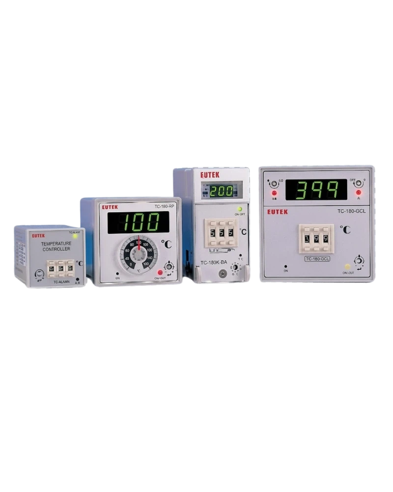
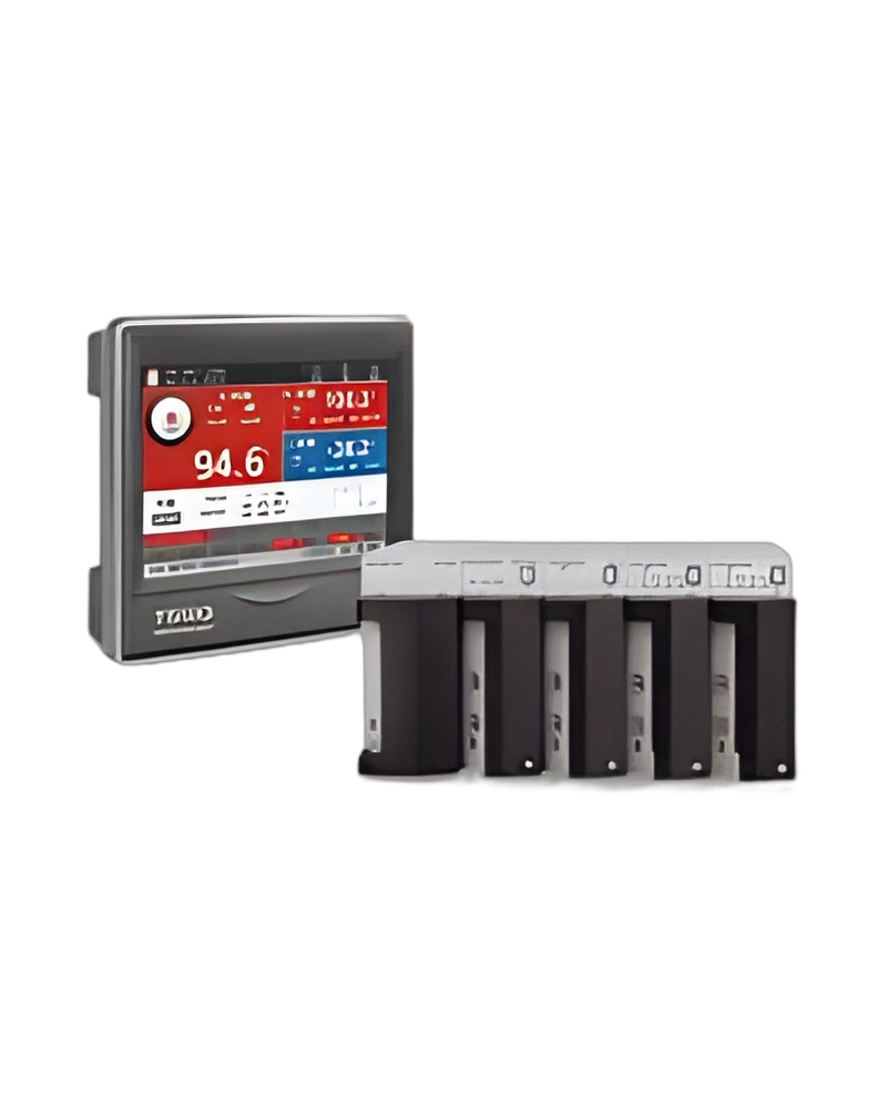
Browse product families and jump into the exact catalog section you need.