
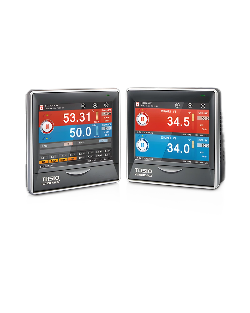
Explore performance details, construction highlights, applications, and technical information in one clear overview.
TH510 is a Hanyoung NUX temperature controller for monitoring and regulating process temperature. The available configuration is built around the listed sensor inputs, control method and output arrangement, with model information of TH510. Input type: Temperature | Humidity; Input type: 2 types of thermoresistor (Pt-100, KPt-100), 2 types of DC voltage (1 - 5 V, 0 - 30 V); Allowable input voltage: DC voltage : ±33 V DC or less; Input type: No-voltage contact input.
For panel and process selection, the important characteristics are the input sensor type, control response, power requirements and display or communication options. Display: TFT color LCD (115.2 × 86.4 mm); Communication type: 2-wire; Synchronization: Asynchronous; Communication distance: Approx. 1.2 km or less.
Key strengths of the TH510 come from the combination of its functional configuration and practical installation specifications. The following characteristics highlight the values that matter most when comparing the product with equipment requirements.
Input type: Temperature | Humidity; Control output: SSR output | ON : 18 V DC Pulse voltage (800 Ω or more load resistance); Power voltage: 100 – 240 V a.c. Voltage regulation ±10 %; Sampling cycle: 250 ms; Display: TFT color LCD (115.2 × 86.4 mm).
The TH510 is specified by its sensor input, control output, electrical supply, sampling behaviour and accuracy. These values determine how the controller measures temperature and applies its selected control response. ON/OFF sensing resistor: Minimum 1㏀ and less: On, maximum 10㏀ and more: Off recognition; Min. sensing time: 0.25 sec; Hysteresis: EUS (0 ~ 100 %); Contact output (DO): Up to 32 relay | A Contact | 30 V d.c. 3 A max, 250 V a.c. 3 A.
Additional technical characteristics include Control output: SSR output | ON : 18 V DC Pulse voltage (800 Ω or more load resistance); SCR output: 4 - 20 mA DC (600 Ω or less load resistance); Transmission output: Current output | 4 - 20 mA DC.
The physical design of TH510 should be considered together with the installation environment and the available mounting or display arrangement. Weight: Approx. 1.32 kg; Dielectric strength: Between 1st and 2nd terminals : Min. 1500 V AC for 1 min Between 1st and FG terminals : Min. 1500 V AC for 1 min Between 2nd and FG terminals : Min. 1500 V AC for 1 min; Insulation resistance: 20 ㏁ or 500 V DC between power and FG terminals; Ambient temperature: 0 ~ 50 ℃.
Further construction and environmental details include Ambient humidity: 20 ~ 90 % RH (Without condensation); Ambient temperature: -20 ~ 70 ℃; Ambient humidity: 5 - 95 % RH (Without condensation).
Integration of TH510 requires the correct sensor input, control output, supply voltage and configuration settings for the application. Communication speed: 9600, 19200, 38400, 57600, 115200 bps; Data Length: 7/8 bits; Protocol: PC-Link / PC-Link+SUM / MODBUS ASC / MODBUS RTU; Language: Korean/English/Chinese(Simplified).
Additional operating and interface details include Output limit: -5.00 - 105.00 %; Output type: Specific value(PV), Setting value(SV), Output(MV), and random; Response Time: 0 - 100 ms. These values provide a practical reference for wiring, setup and normal operation within the selected configuration.
Choose TH510 by confirming the exact model or configuration against the required operating conditions. The available model information is TH510. Scaling: DC voltage(VDC) : Input scaling according to conversion range; Scaling: Auto scaling for defined upper/lower limit range (4 - 20 mA DC); Measuring range (℃): accuracy | Measuring range (%RH) | accuracy; Sampling cycle: 250 ms.
Before installation, confirm Control output: Temperature control output | SSR output or SCR (4 - 20 mA DC) output; Transmission output: Temperature, Humidity | 4 - 20 mA d.c. Specific value(PV), Setting value(SV) and Output(MV); Power voltage: 100 – 240 V a.c. Voltage regulation ±10 %. Matching the model, electrical ratings, signal requirements, physical arrangement and environmental limits helps keep the product within its specified operating conditions.
| Specification | Details |
|---|---|
| Input type | Temperature | Humidity |
| Measuring range (℃) | accuracy | Measuring range (%RH) | accuracy |
| Thermo resistor (RTD) | Pt100 Ω | Pt-1 | -100.0 ~ 300.0 | ±0.1 % of F.S ±1 Digit | 0.0 ~ 100.0 | ±1 % of F.S ±1 Digit |
| Pt-2 | -100.00 ~ 150.00 |
| KPt100 Ω | KPt-1 | -100.0 ~ 300.0 |
| KPt-2 | -100.00 ~ 150.00 |
| DC voltage (VDC) | 1 - 5 V | -100.0 ~ 300.0 | ±0.1 % of F.S ±1 Digit |
| 0 - 30 V | -100.0 ~ 300.0 |
| Power voltage | 100 – 240 V a.c. Voltage regulation ±10 % |
| Power frequency | 50 - 60 ㎐ |
| Power consumption | 30 VA max |
| Max. rating of internal fuse | 250 V a.c. |
| Dielectric strength | Between 1st and 2nd terminals : Min. 1500 V AC for 1 min Between 1st and FG terminals : Min. 1500 V AC for 1 min Between 2nd and FG terminals : Min. 1500 V AC for 1 min |
| Insulation resistance | 20 ㏁ or 500 V DC between power and FG terminals |
| Input type | 2 types of thermoresistor (Pt-100, KPt-100), 2 types of DC voltage (1 - 5 V, 0 - 30 V) |
| Sampling cycle | 250 ms |
| Measured current of thermoresistor(RTD) | Approx. 0.21 mA |
| Input resistance | DC voltage : 1 ㏁ or more |
| Allowable wire resistance | Thermoresistor : Max. 10Ω/wire, DC voltage : 2 ㏀ or less |
| Influence of wire resistance | Thermoresistor : ±0.3 ℃/10 Ω (3 wires must have the same wire resistance) |
| Allowable input voltage | DC voltage : ±33 V DC or less |
| Detection of sensor disconnection (Burn-out) | UP-Scale for disconnection |
| Contact output (DO) | Up to 32 relay | A Contact | 30 V d.c. 3 A max, 250 V a.c. 3 A |
| B Contact | NO : 30 V d.c. 5 A max, 250 V a.c. 5 A |
| Control output | SSR output | ON : 18 V DC Pulse voltage (800 Ω or more load resistance) |
| SCR output | 4 - 20 mA DC (600 Ω or less load resistance) |
| Transmission output | Current output | 4 - 20 mA DC |
| Load resistance | 600 Ω or less load resistance |
| Output limit | -5.00 - 105.00 % |
| Output type | Specific value(PV), Setting value(SV), Output(MV), and random |
| Refresh interval | 250 ms |
| Max. number of input | 32 Contacts |
| Input type | No-voltage contact input |
| ON/OFF sensing resistor | Minimum 1㏀ and less: On, maximum 10㏀ and more: Off recognition |
| Min. sensing time | 0.25 sec |
| Operational conditions | During operation/Always |
| Contact function | Operation and stop/hold/step by DI ; User can define error screen. |
| Applied standard | RS485 |
| Max. connection number | 1:32 (address 1 ~ 99) |
| Communication type | 2-wire |
| Synchronization | Asynchronous |
| Communication distance | Approx. 1.2 km or less |
| Communication speed | 9600, 19200, 38400, 57600, 115200 bps |
| Data Length | 7/8 bits |
| Parity Bit | NONE / EVEN / ODD |
| Stop Bit | 1/2 bit(s) |
| Protocol | PC-Link / PC-Link+SUM / MODBUS ASC / MODBUS RTU |
| Response Time | 0 - 100 ms |
| Input | Input calibration (Sensor bias) | 1 Temperature contact : EUS(0 ~ 100 %) 1 Humidity contact : EUS(0 ~ 100 %) |
| Dry/wet-bulb sensor compensation | Compensate the dry/wet sensor difference after removing the gauze of the wet-bulb sensor. |
| Scaling | DC voltage(VDC) : Input scaling according to conversion range |
| Input filter (LPF) | 0 ~ 120 sec |
| Control mode | Operation type | Constant-value / Program control |
| Control output | Temperature control output | SSR output or SCR (4 - 20 mA DC) output |
| Control operation | Pattern | 100 patterns(1 pattern/100 segments) |
| Segment | 2000 segments |
| PID Group | 16 groups (temperature 4 zones X humidity 4 zones) |
| Auto tuning | Auto tuning according to target setting value |
| Proportional band | 0.00 ~ 100.00 % (For 0.00 %, ON/OFF control) |
| Integral time | 0.0 ~ 3,000 sec (OFF when 0 sec) |
| ON/OFF control | Set 0.0 to proportional band(PB) |
| Normal Open/Normal Close | According to selection of Normal Open / Normal Close for control output |
| Hysteresis | EUS (0 ~ 100 %) |
| Transmission output | Temperature, Humidity | 4 - 20 mA d.c. Specific value(PV), Setting value(SV) and Output(MV) |
| Scaling | Auto scaling for defined upper/lower limit range (4 - 20 mA DC) |
| Alarm setting | Alarm setting | System alarm : 8 points Assign 4 of 8 pattern alarms to a pattern |
| Alarm type | Absolute high/low limit, deviation high/low limit, in range/out of range (alarm direction, hold) |
| Absolute alarm setting range | EU (0 ~ 100 %) |
| Offset information setting range | EUS (-100 ~ 100 %) |
| Display | TFT color LCD (115.2 × 86.4 mm) |
| Number of Pixels | 640 × 480 pixel |
| Back light | LED back light |
| Life cycle of back light | Approx. 40,000 h |
| Touch type | Resistive type (4 Wires) |
| Language | Korean/English/Chinese(Simplified) |
| Internal memory | Non-volatile memory : 80 MB – Saving of 15 days at 1 S interval |
| External memory | SD card(2 GB) : Saving of 1 year at 1 S interval |
| Saving interval | 1 ~ 360 sec |
| Memory information | Program information, setting value, recovery, and temperature setting/ specific/output value |
| Ambient temperature | 0 ~ 50 ℃ |
| Temperature fluctuation | 10 ℃/h or less |
| Ambient humidity | 20 ~ 90 % RH (Without condensation) |
| Magnetic field | 400 A/m or less |
| Altitude | 2,000 m or less from the sea |
| Weight | Approx. 1.32 kg |
| Ambient temperature | -20 ~ 70 ℃ |
| Temperature fluctuation | 20 ℃/h or less |
| Ambient humidity | 5 - 95 % RH (Without condensation) |
| DC voltage | ±0.003 % of F.S / ℃ |
| Thermoresistor sensor | ±0.03 ℃/℃ |
| No | Type | Category | Title | File |
| 1 | Manual > User Manual | Temperature Controllers | TH510 User manual |
| 2 | Manual > Catalogue | Temperature Controllers | TH510 Catalogue |
| 1 | CAD > 2D | Temperature Controllers | TH510 (2D) |
| 2 | CAD > 3D | Temperature Controllers | TH510 (3D) |
| 1 | Software > Program | ALL | Communication Protocol Examples |
| No | Mark | Category | Title | File |
| 1 | Certification > CE | Temperature Controllers | TD510 / TH510 / TS510 (EMC) |
| Between 1st and 2nd terminals | Min. 1500 V AC for 1 min |
| Between 1st and FG terminals | Min. 1500 V AC for 1 min |
| Between 2nd and FG terminals | Min. 1500 V AC for 1 min |
| DC voltage | 1 ㏁ or more |
| DC voltage | ±33 V DC or less |
| 1 Temperature contact | EUS(0 ~ 100 %) |
| 1 Humidity contact | EUS(0 ~ 100 %) |
| DC voltage(VDC) | Input scaling according to conversion range |
| System alarm | 8 points |
| Non-volatile memory | 80 MB – Saving of 15 days at 1 S interval |
Browse product families and jump into the exact catalog section you need.