
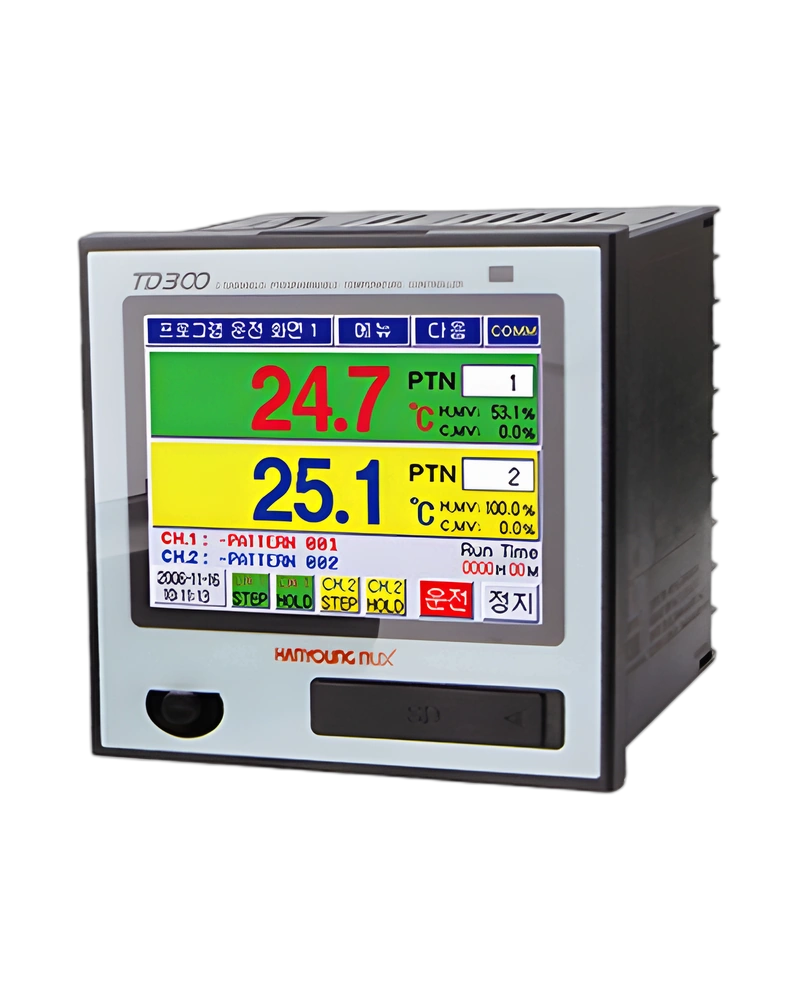
Explore performance details, construction highlights, applications, and technical information in one clear overview.
TD300 Programmable Temperature Controller is a Hanyoung NUX temperature controller for monitoring and regulating process temperature. The available configuration is built around the listed sensor inputs, control method and output arrangement, with model information of TD300 Programmable Temperature Controller. Control Output: SCR | 4 - 20 mA d.c. (Resistive load : less than 600 Ω) Output Resolution : 16 bit Accuracy of Output : ±0.1 % of FS Output Ripple : 0.2 % of FS; Relay Output: Internal relay specification : NO -> 250 V a.c. 5 A / 30 V d.c. 5 A; Transmission Output (4 - 20 mA): Avaliable to select PV / SV / H.MV / C.MV of each channel Output Accuracy : ±0.1 % of FS In case of heating/cooling control, if control output of heating is SCR or SSR, this channel can not use transmission output.; Transmission Output Period of output renewal: 500 ms.
For panel and process selection, the important characteristics are the input sensor type, control response, power requirements and display or communication options. Accuracy of indication: 0.1 ℃; User Logo Display: User logo could be shown for 3 sec after power on. Download through communication port; Control Method: Heating control or Heating/Cooling control in each channel. PID or ON/OFF control; Language: Korean and English.
Key strengths of the TD300 Programmable Temperature Controller come from the combination of its functional configuration and practical installation specifications. The following characteristics highlight the values that matter most when comparing the product with equipment requirements.
Input (2 channels): Pt100 (IEC751) | -200 ~ 640 ℃, ±0.1 % of FS; Control Method: Heating control or Heating/Cooling control in each channel. PID or ON/OFF control; Control Output: SCR | 4 - 20 mA d.c. (Resistive load : less than 600 Ω) Output Resolution : 16 bit Accuracy of Output : ±0.1 % of FS Output Ripple : 0.2 % of FS; Sampling cycle: Each channel 500 msec; User Logo Display: User logo could be shown for 3 sec after power on. Download through communication port.
The TD300 Programmable Temperature Controller is specified by its sensor input, control output, electrical supply, sampling behaviour and accuracy. These values determine how the controller measures temperature and applies its selected control response. Contact Output: Output of various signals; Delayed Response Time: RS232 RS422/485 | 1 + (0 ~ 250) ms; Analog Output: Less than ±0.05 % of FS / ℃; Output Resolution: 16 bit.
Additional technical characteristics include Accuracy of Output: ±0.1 % of FS; Output Ripple: 0.2 % of FS; Avaliable to select PV / SV / H.MV / C.MV of each channel Output Accuracy: ±0.1 % of FS.
The physical design of TD300 Programmable Temperature Controller should be considered together with the installation environment and the available mounting or display arrangement. Insulation resistance: Between 1st & 2nd Terminal 1st/2nd and Earth Terminal | More than 10 MΩ / 500V d.c.; Dielectric strength: Between 1st & 2nd Terminal 1st/2nd and Earth Terminal | 2500 V a.c. 50 / 60 Hz, 1 min.; Short time Vibration: Below 14.7 m/s 15 sec (Each 3 directions); Shock: Below 147 m/s 11 msec (Each 6 directions, 3 times).
Further construction and environmental details include Shock: Less than 1 m when dropping the packed product; Communication Method: RS232 RS422/485 | Full Duplex 4 wired Half Duplex, 2 wired Half Duplex; Communication Distance: RS232 RS422/485 | Within approximately 10 m Within approximately 1.2 Km.
Integration of TD300 Programmable Temperature Controller requires the correct sensor input, control output, supply voltage and configuration settings for the application. Communication Speed: RS232 RS422/485 | 9600 ~ 38400 bps; Communication Protocol: RS232 RS422/485 | PCLinkSUM + CHECK SUM; Communication: 1 | RS485/422 communication; Language: 1 | Korean and English (Standard type).
Additional operating and interface details include Rated Voltage: 100 - 240 V a.c., Valiable Voltage Ratio : ± 10 %; Power Consumption: Max. 10 W; Sampling cycle: Each channel 500 msec. These values provide a practical reference for wiring, setup and normal operation within the selected configuration.
Choose TD300 Programmable Temperature Controller by confirming the exact model or configuration against the required operating conditions. The available model information is TD300 Programmable Temperature Controller. Input (2 channels): Pt100 (IEC751) | -200 ~ 640 ℃, ±0.1 % of FS; Control Method: Heating control or Heating/Cooling control in each channel. PID or ON/OFF control; Control Output: SCR | 4 - 20 mA d.c. (Resistive load : less than 600 Ω) Output Resolution : 16 bit Accuracy of Output : ±0.1 % of FS Output Ripple : 0.2 % of FS; Sampling cycle: Each channel 500 msec.
Before installation, confirm User Logo Display: User logo could be shown for 3 sec after power on. Download through communication port; Power Consumption: Max. 10 W; Communication Method: RS232 RS422/485 | Full Duplex 4 wired Half Duplex, 2 wired Half Duplex. Matching the model, electrical ratings, signal requirements, physical arrangement and environmental limits helps keep the product within its specified operating conditions.
| Specification | Details |
|---|---|
| Input (2 channels) | Pt100 (IEC751) | -200 ~ 640 ℃, ±0.1 % of FS |
| TC_K | -200 ~ 1370 ℃, ±0.1 % of FS |
| TC_J | -200 ~ 1200 ℃, ±0.1 % of FS |
| TC_E | -200 ~ 1000 ℃, ±0.1 % of FS |
| TC_T | -200 ~ 400 ℃, ±0.1 % of FS |
| TC_R | 0 ~ 1700 ℃, ±0.15 % of FS |
| TC_S | 0 ~ 1700 ℃, ±0.15 % of FS |
| mV | 0 ~ 100 mV or -10 ~ 20 mV (-999.9 ~ 9999.9), ±0.1 % of FS |
| VDC | 0 - 10 V (Signal Input Range setup is available, -999.9 ~ 9999.9), ±0.1 % of FS |
| 4 - 20 mA | Use 250 Ω external resistance, VDC Use after setup of 1 - 5 V d.c. |
| Input Resolution | 24 bit |
| Accuracy of indication | 0.1 ℃ |
| Sampling cycle | Each channel 500 msec |
| Input Resistance | More than 1 MΩ |
| Maximum allowable resistance of line | Less than 50 Ω / Line (Resistance of lines is a same condition) |
| RJC | ±1.5 ℃ |
| Control Output | SCR | 4 - 20 mA d.c. (Resistive load : less than 600 Ω) Output Resolution : 16 bit Accuracy of Output : ±0.1 % of FS Output Ripple : 0.2 % of FS |
| SSR | 24 V d.c. Pulse (Resistive load : More than 600 Ω) Min. Pulse Range : 10 ms Cycle Time : Available to select 1 - 1000 s |
| Relay Output | Internal relay specification : NO -> 250 V a.c. 5 A / 30 V d.c. 5 A |
| Transmission Output (4 - 20 mA) | Avaliable to select PV / SV / H.MV / C.MV of each channel Output Accuracy : ±0.1 % of FS In case of heating/cooling control, if control output of heating is SCR or SSR, this channel can not use transmission output. |
| Transmission Output Period of output renewal | 500 ms |
| Screen | TD300 | 3.5 Inch Color LCD and Interface with Touch Panel |
| Pattern | Max. 100 , Available to operate each channel's pattern |
| Segment | Max. 2,400 (Max 100 per segment) |
| Waiting Mode | Setup per pattern and setup of using or not using per segment |
| Repetition & Connection | Available to use Pattern Repetition and Section Repeat Loof Setup (Max. 20) Free connecting operation among patterns is available |
| PID Group | Each channel 4 Zones, Selectable between manual or automatic |
| Control Method | Heating control or Heating/Cooling control in each channel. PID or ON/OFF control |
| Auto Tuning | Optimal PID GAIN is automatically calculated according to Set Value. It could be operated by each channel |
| Proportional Band | 0.0 ~ 1000.0 ℃ (If "0" = On/Off control, Not "0" = PID control) |
| Integral Time | 0 ~ 6000 sec ("0" = No Integral Calculation) |
| Differential Time | 0 ~ 6000 sec ("0" = No Differential Calculation) |
| ON/OFF control | Available to select Dead zone 0.1 ~ 1000.0 ℃ |
| Event Log | Max. 40 Event Logs could be saved depending on various situations |
| LCD protection | Back light will be off according to designated time of not using touch panel |
| Password | Password is available to prevent other people from changing system setup |
| Protection of Over-Integral and Differential | ARW Zone setup (50 ~ 200 % of proportional band) |
| Fuzzy Function | Control overshoot |
| RAMP | Available to select SV changing ratio in case of fixing operation |
| Restrict MV changing ratio | Function to control sudden change of MV |
| Alarm Setup | 4 points, High, Low, Deviation etc. 20 kinds |
| Inner Signal | 8 points, object, range and delayed time setup are available |
| Time Signal | 8 points when program mode operation |
| Graph Function | PV, SV of each channel could be display by graph |
| Fixing Operation Hour | Available to set fixing operation hour up |
| Reservation Operation Fuction | Available to use reservation operation time by using built in timer. |
| User Logo Display | User logo could be shown for 3 sec after power on. Download through communication port |
| Screen Capture | Upload is available through communication port |
| Language | Korean and English |
| Contact Input | RUN/STOP, STEP, HOLD and Error Input (Stop operation, Delayed/ setup is available) |
| Contact Output | Output of various signals |
| Storage in Power Failure | Various setting and operation information memory |
| Return from Power Failure | STOP / COLD / HOT return when power failure is restored |
| Applied Standard | EIA-RS232C, EIA-RS422/485, USB |
| Max.Connection Number | RS232 RS422/485 | 1 : 1 1 : 256 |
| Communication Method | RS232 RS422/485 | Full Duplex 4 wired Half Duplex, 2 wired Half Duplex |
| Synchronous Method | RS232 RS422/485 | asynchronous |
| Communication Distance | RS232 RS422/485 | Within approximately 10 m Within approximately 1.2 Km |
| Communication Speed | RS232 RS422/485 | 9600 ~ 38400 bps |
| Length of Data | RS232 RS422/485 | 8 bits |
| Parity Bit | RS232 RS422/485 | NONE |
| Stop Bit | RS232 RS422/485 | 1 bit(s) |
| Communication Protocol | RS232 RS422/485 | PCLinkSUM + CHECK SUM |
| Delayed Response Time | RS232 RS422/485 | 1 + (0 ~ 250) ms |
| Rated Voltage | 100 - 240 V a.c., Valiable Voltage Ratio : ± 10 % |
| Frequecy | 50 - 60 Hz |
| Power Consumption | Max. 10 W |
| Insulation resistance | Between 1st & 2nd Terminal 1st/2nd and Earth Terminal | More than 10 MΩ / 500V d.c. |
| Dielectric strength | Between 1st & 2nd Terminal 1st/2nd and Earth Terminal | 2500 V a.c. 50 / 60 Hz, 1 min. |
| Installation | Continuous Vibration | Vibration Wide : Bleow 1.2 mm (5 - 14 Hz) Below 4.9 m/s (4 - 150 Hz) |
| Short time Vibration | Below 14.7 m/s 15 sec (Each 3 directions) |
| Shock | Below 147 m/s 11 msec (Each 6 directions, 3 times) |
| Normal Operation Condition | Surrounding Temperature | 0 ~ 50 ℃ |
| Surrounding Humidity | 20 ~ 90 % RH (No Condensation) |
| Magnetic Effect | Less than 400 AT/m |
| Preheating | More than 10 minute |
| Effect of surrounding temperature | Voltage/TC Input | ±1 uV / ℃ or ±0.01 % of FS / ℃ |
| RTD Input | Less than ±0.05 ℃ / ℃ |
| Analog Output | Less than ±0.05 % of FS / ℃ |
| Temperature | -25 ~ 70 ℃ |
| Humidity | 5 ~ 95 % RH (No condensation) |
| Shock | Less than 1 m when dropping the packed product |
| Model | Code | Information |
| TD300 | Programmable Temperature Controller (DIN 96 × 96) |
| Communication | 1 | RS485/422 communication |
| 2 | RS232C communication |
| Language | 1 | Korean and English (Standard type) |
| 2 | English and Chinese (Simplified Chinese Characters) |
| No | Type | Category | Title | File |
| 1 | Manual > User Manual | Temperature Controllers | TD300 User manual |
| 1 | CAD > 2D | Temperature Controllers | TD300 (2D) |
| 2 | CAD > 3D | Temperature Controllers | TD300 (3D) |
| 1 | Software > Program | ALL | Communication Protocol Examples |
| 2 | Software > Communication data | Temperature Controllers | TD300/TD500 communication protocol |
| No | Mark | Category | Title | File |
| 1 | Certification > CE | Temperature Controllers | TD300 (EMC) TD300 (EMC) |
| 4 - 20 mA d.c. (Resistive load | less than 600 Ω) |
| Output Resolution | 16 bit |
| Accuracy of Output | ±0.1 % of FS |
| Output Ripple | 0.2 % of FS |
| 24 V d.c. Pulse (Resistive load | More than 600 Ω) |
| Min. Pulse Range | 10 ms |
| Internal relay specification | NO -> 250 V a.c. 5 A / 30 V d.c. 5 A |
| Avaliable to select PV / SV / H.MV / C.MV of each channel Output Accuracy | ±0.1 % of FS |
| 100 - 240 V a.c., Valiable Voltage Ratio | ± 10 % |
Browse product families and jump into the exact catalog section you need.