
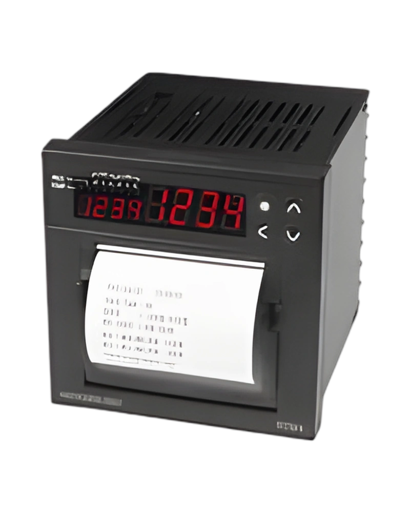
Explore performance details, construction highlights, applications, and technical information in one clear overview.
RT9N is a Hanyoung NUX recorder designed for industrial measurement, indication and process monitoring. Its configuration is determined by the available input signals, measurement or recording functions, display and output characteristics, with model information of RT9N. Allowable signal source resistance: Thermocouple : 250 Ω max., voltage : 2 kΩ max; Allowable input voltage: - Within ±10 V (thermocouple, RTD, voltage: mV d.c.) - Within ±20 V (voltage: V d.c.); Alarm output: Relay contact output | - Contact capacity : 240 V a.c. 1 A, 30 V d.c. 1 A (resistive load) - Contact configuration : 1a - Output contacts: 2 (AL1, AL2); SSR output (voltage pulse output): - ON voltage : approx. 12 V d.c. min. (load resistance 400 Ω, approx. 30 mA current limit during short circuit) - OFF voltage : 0.1 V d.c. max., proportional cycle : 1 ~ 1,000 sec. - Output operation : PID - Output limit : 0.0~100.0% range high limit (OH),low limit (OL) selectable,also during auto-tuning. - Time resolution : lower between 0.1% or 10 ms..
The listed measurement range, accuracy, input method, display format and connection details provide the main selection points for panel and control-system integration. Input display resolution: Basically below the decimal point of "Measurement range index"; Display and record accuracy: ±0.5% (Full Scale); Communication method: 2-wire half-duplex; Synchronization: Asynchronous.
Key strengths of the RT9N come from the combination of its functional configuration and practical installation specifications. The following characteristics highlight the values that matter most when comparing the product with equipment requirements.
Number of channels: 1 | 1 channel; Accuracy: Display and record accuracy: ±0.5% (Full Scale); - Recording speed: 20, 30, 60, 120, 180, 300, 600, 900 mm/h; Alarm output: Relay contact output | - Contact capacity : 240 V a.c. 1 A, 30 V d.c. 1 A (resistive load) - Contact configuration : 1a - Output contacts: 2 (AL1, AL2); Power voltage: 100 - 240 V a.c. (voltage fluctuation rate ±10% ).
The RT9N technical profile combines measurement inputs, channel capacity, sampling, accuracy, recording functions and control outputs. These parameters determine how process values can be monitored and recorded. SCR output (4-20 mA d.c.): - Load resistance: 400 Ω max. - Accuracy : ±0.5% of max. scale (4 - 20 mA range), resolution : approx. 3,000 - Output ripple : max. ±0.3% (P-P) of max. scale (150 Hz) - Output sampling cycle : 250 ms, output operation: continuous PID - Output limit: -5.0~105.0% range high limit (OH),low limit (OL) selectable,also during auto-tuning; Alarm output: - Set contacts : 2 (1 contact per channel, 1-channel type only supports alarm 1 contact) - Alarm types : high/low, high/low deviation, hold high/low, heater break (refer to "alarm type and code" table) - Setting range : during absolute value alarm 0 ~ 100% of instrument range during deviation alarm -100 ~ 100% of instrument range; RESPONSE TIME: Reception handling time + (response time × 10 ms); - Contact capacity: 240 V a.c. 1 A, 30 V d.c. 1 A (resistive load).
Additional technical characteristics include - Output contacts: 2 (AL1, AL2); - Contact capacity: 240 V a.c. 3 A, 30 V d.c. 3 A (resistive load), contact configuration : 1C; - Output operation: PID, ON/OFF, proportional cycle : 1 ~ 1,000 sec..
The physical design of RT9N should be considered together with the installation environment and the available mounting or display arrangement. - Panel dimensions: refer to "dimension and panel cutout"; Ambient temperature influence: - Thermocouple, voltage input : ±1 μV/℃ or ±0.01%/℃ of max. range - RTD input : ±0.05 Ω/℃ max. - Analog output : Max. ±0.05%/℃ of max. range (continuous output); Insulation resistance: Between primary terminal and secondary terminal: 500 V d.c. 20 MΩ min. Between primary terminal and ground: 500 V d.c. 20 MΩ min. Between secondary terminal and ground: 500 V d.c. 20 MΩ min.; Dielectric strength: Between primary terminal and secondary terminal: 2,300 V a.c. 50/60 Hz for 1 minute Between primary terminal and ground: 2,300 V a.c. 50/60 Hz for 1 minute Between secondary terminal and F•G: 1,500 V a.c. 50/60 Hz for 1 minute.
Further construction and environmental details include Storage temperature: -25 ~ 70℃; Shock: 1 m max. in packed condition (natural fall); - Continuous vibration (5 - 14 Hz): Forward width 1.2 mm. max.,.
Integration of RT9N begins with matching its connection, input or control signal and output requirements to the surrounding equipment. Communication sequence: None; Communication distance: Within 1.2 km; Communication speed: 2400(setting value 2), 4800(setting value 3) , 9600(setting value 4), 14400(setting value 5), 19200(setting value 6) (communication speed changes by parameter settings); PROTOCOL: PC LINK(setting value 0), PC LINK SUM(setting value 1), MODBUS-ASCIl(setting value 2), MODBUS-RTU(setting value 3).
Additional operating and interface details include - Output limit: 0.0~100.0% range high limit (OH), low limit (OL) selectable,also during auto-tuning.; - Output operation: PID; - Output limit: 0.0~100.0% range high limit (OH),low limit (OL) selectable,also during auto-tuning.. These values provide a practical reference for wiring, setup and normal operation within the selected configuration.
Choose RT9N by confirming the exact model or configuration against the required operating conditions. The available model information is RT9N. Standard: EIA RS485; Model: Code | Content; Sampling cycle: 250 ms; Accuracy: Display and record accuracy: ±0.5% (Full Scale).
Before installation, confirm - Accuracy: ±0.5% of max. scale (4 - 20 mA range), resolution : approx. 3,000; - Recording speed: 20, 30, 60, 120, 180, 300, 600, 900 mm/h; - Output ripple: max. ±0.3% (P-P) of max. scale (150 Hz). Matching the model, electrical ratings, signal requirements, physical arrangement and environmental limits helps keep the product within its specified operating conditions.
| Specification | Details |
|---|---|
| Input types | Thermocouple : K, J, E, T, R, B, S, L, N, U, WRe 5-26, PL-Ⅱ (Refer to input signal and measurement range) RTD : Pt 100 Ω, KSPt 100 Ω DC voltage input : 1 - 5 V d.c., 0 - 10 V d.c., -10 ~ 20 mV d.c., 0 - 100 mV d.c. (Free scale method) ⚠️ Notice When using a current input, this product functions properly only with voltage divider feedback. Therefore, be sure to check whether the circuit uses current-sensing feedback or voltage divider feedback before use. However, if only one channel is used, both feedback methods are supported. |
| Sampling cycle | 250 ms |
| Input display resolution | Basically below the decimal point of "Measurement range index" |
| Input impedance | Thermocouple and DC voltage input (mV) : 1 MΩ min.,DC voltage input(V): approx. 1 MΩ |
| Allowable signal source resistance | Thermocouple : 250 Ω max., voltage : 2 kΩ max |
| Allowable wiring resistance | - RTD : 10 Ω max./wire (conductor resistance among 3 wires should be the same) |
| Allowable input voltage | - Within ±10 V (thermocouple, RTD, voltage: mV d.c.) - Within ±20 V (voltage: V d.c.) |
| Noise removal rate | - NMRR (normal mode) : 40 dB min. (50/60 Hz ±1%) - CMRR (common mode) : 120 dB min. (50/60 Hz ±1%) |
| Standards | - Thermocouple/RTD (KS/IEC/DIN) |
| Standard contact compensation tolerance | ±1.5 ℃ (15 ~ 35 ℃), ±2.0 ℃ (0 ~ 50 ℃) |
| Input discon nection detection (BURN-OUT) | - Thermocouple : OFF, UP/DOWN scale selectable - RTD: UP Scale (detection current during thermocouple and RTD BURN- OUT: approx. 50 mA) |
| Accuracy | Display and record accuracy: ±0.5% (Full Scale) |
| Input range | Refer to “Input signal and measurement range”. Thermocouple and RTD can be changed within the range of input signal and measurement range chart. DC voltage can change the minimum voltage and maximum voltage within each range. Scaling possible within the conditions of measurement range. |
| Alarm output | Relay contact output | - Contact capacity : 240 V a.c. 1 A, 30 V d.c. 1 A (resistive load) - Contact configuration : 1a - Output contacts: 2 (AL1, AL2) |
| Control output | Relay contact output | - Contact capacity : 240 V a.c. 3 A, 30 V d.c. 3 A (resistive load), contact configuration : 1C - Output operation : PID, ON/OFF, proportional cycle : 1 ~ 1,000 sec. - Output limit : 0.0~100.0% range high limit (OH), low limit (OL) selectable,also during auto-tuning. - ON/OFF hysteresis : 0 ~ 100% (Full Scale) - Time resolution : lower between 0.1% or 10 ms |
| SSR output (voltage pulse output) | - ON voltage : approx. 12 V d.c. min. (load resistance 400 Ω, approx. 30 mA current limit during short circuit) - OFF voltage : 0.1 V d.c. max., proportional cycle : 1 ~ 1,000 sec. - Output operation : PID - Output limit : 0.0~100.0% range high limit (OH),low limit (OL) selectable,also during auto-tuning. - Time resolution : lower between 0.1% or 10 ms. |
| SCR output (4-20 mA d.c.) | - Load resistance: 400 Ω max. - Accuracy : ±0.5% of max. scale (4 - 20 mA range), resolution : approx. 3,000 - Output ripple : max. ±0.3% (P-P) of max. scale (150 Hz) - Output sampling cycle : 250 ms, output operation: continuous PID - Output limit: -5.0~105.0% range high limit (OH),low limit (OL) selectable,also during auto-tuning |
| Measure ment input | - Input calibration (Bias) : -100.0 ~ 100.0 % for instrument range (can calibrate the desired correction value to the measurement input value) - Scaling: measurement range scaling is possible according to maximum value (SH) and minimum value (SL) settings of measurement range. - Input filter: OFF, 1 ~ 120 sec. |
| Control | PID groups : 3 types - PID groups : 3 types - Auto-tuning : auto-tuning operates according to set value (SV) (standard type, low PV type) - Proportional band : 0.1 ~ 999.9% (max. range) - Integral time : OFF, 1 ~ 6000 sec. - Derivative time : OFF, 1 ~ 6000 sec. - ON/OFF control : by selecting output code (OT) “1” - PID selection : ZONE PID / Auto 1, 2, 3 selectable. - Manual reset : -5.0 ~ 105.0% of output (valid only when integral time is “OFF”) - Direct /reverse action selection: selectable by parameter. - Emergency output value : -5.0 ~ 105.0% of output value - ON/OFF hysteresis (HYS) : 0.0~100.0% of instrument range (however, valid only if set to ON/OFF control) - ARW (Anti Reset Wind-up) : AUTO, 50.0 ~ 200.0% - Fuzzy function: ON or OFF selection by parameter - Ramp function: the rising temperature and falling temperature gradient can be set in hours or minutes when the power is on. |
| Alarm output | - Set contacts : 2 (1 contact per channel, 1-channel type only supports alarm 1 contact) - Alarm types : high/low, high/low deviation, hold high/low, heater break (refer to "alarm type and code" table) - Setting range : during absolute value alarm 0 ~ 100% of instrument range during deviation alarm -100 ~ 100% of instrument range |
| Record | - Measuring points: 1 - Response time : according to record speed - Record type : thermal line - Printing method : 203 dpi (8.0 dots/mm) 384 dots per line - Recording speed : 20, 30, 60, 120, 180, 300, 600, 900 mm/h - Recorder paper check: if there is no paper the front display window P-END lamp turns on and record stops. - Recorder paper : width 57.5 mm, length approx. 16 m |
| Installation environment | - Continuous vibration (5 - 14 Hz) : Forward width 1.2 mm. max., - Continuous vibration (4 ~ 150 Hz): 4.9 m/s² max. - Chort-time vibration : 14.7 m/s² , 15 sec. max. (each of 3 directions) - Shock: 147 m/s², 11 ms max. (6 directions each 3 times) - Panel dimensions: refer to "dimension and panel cutout" |
| Normal operating conditions | - Ambient temperature : 0 ~ 50 ℃ - Ambient humidity : 35 ~ 85 %RH (with no condensation) - Magnetic influence : 400 AT/m max. - Warm-up time : 30 minutes min. |
| Ambient temperature influence | - Thermocouple, voltage input : ±1 μV/℃ or ±0.01%/℃ of max. range - RTD input : ±0.05 Ω/℃ max. - Analog output : Max. ±0.05%/℃ of max. range (continuous output) |
| Power voltage | 100 - 240 V a.c. (voltage fluctuation rate ±10% ) |
| Power frequency | 50 - 60 Hz |
| Power consumption | 15 W max., 20 VA max. |
| Insulation resistance | Between primary terminal and secondary terminal: 500 V d.c. 20 MΩ min. Between primary terminal and ground: 500 V d.c. 20 MΩ min. Between secondary terminal and ground: 500 V d.c. 20 MΩ min. |
| Dielectric strength | Between primary terminal and secondary terminal: 2,300 V a.c. 50/60 Hz for 1 minute Between primary terminal and ground: 2,300 V a.c. 50/60 Hz for 1 minute Between secondary terminal and F•G: 1,500 V a.c. 50/60 Hz for 1 minute |
| Storage temperature | -25 ~ 70℃ |
| Storage humidity | 5 ~ 95% RH (with no condensation) |
| Shock | 1 m max. in packed condition (natural fall) |
| Standard | EIA RS485 |
| Maximum number of connections | max. 31 (1 ~ 99 address settings available) |
| Communication method | 2-wire half-duplex |
| Synchronization | Asynchronous |
| Communication sequence | None |
| Communication distance | Within 1.2 km |
| Communication speed | 2400(setting value 2), 4800(setting value 3) , 9600(setting value 4), 14400(setting value 5), 19200(setting value 6) (communication speed changes by parameter settings) |
| START BIT | 1 BIT |
| DATA BIT | 7 or 8 BIT |
| PARITY BIT | None, Even Numbers, Odd numbers |
| STOP BIT | 1 or 2 BIT |
| PROTOCOL | PC LINK(setting value 0), PC LINK SUM(setting value 1), MODBUS-ASCIl(setting value 2), MODBUS-RTU(setting value 3) |
| RESPONSE TIME | Reception handling time + (response time × 10 ms) |
| Model | Code | Content |
| RT9N- | 2-channel temperature controller & recorder 96(W) × 96(H) |
| Control type | 0 | Temperature record only |
| 1 | Temperature record & control |
| Number of channels | 1 | 1 channel |
| 2 | 2 channels | Only control the same output type |
| Options | 0 | None (AL1 built-in) |
| 1 | AL2 | only for 1-channel models |
| 2 | AL2, communication (RS485) |
| 3 | Communication (RS485) |
| No | Type | Category | Title | File |
| 1 | Manual > Instruction Manual | Recorder | RT9N Instruction manual |
| 1 | CAD > 3D | Recorder | RT9N (3D) |
| 1 | Software > Program | ALL | Communication Protocol Examples |
| 2 | Software > Program | ALL | TCS Integrated Communication Program Installation file |
| 3 | Software > Program | Recorder | RT9 KV/EV2.0.0 (Kr,En) |
| 4 | Software > Communication data | Recorder | RT9N register address |
| 5 | Software > Communication data | ALL | TCS Integrated Communication Program Manual(EN) |
| DC voltage input | 1 - 5 V d.c., 0 - 10 V d.c., -10 ~ 20 mV d.c., 0 - 100 mV d.c. (Free scale method) |
| Thermocouple and DC voltage input (mV) | 1 MΩ min.,DC voltage input(V): approx. 1 MΩ |
| - Within ±10 V (thermocouple, RTD, voltage | mV d.c.) |
| - Within ±20 V (voltage | V d.c.) |
| Display and record accuracy | ±0.5% (Full Scale) |
| - Contact capacity | 240 V a.c. 1 A, 30 V d.c. 1 A (resistive load) |
| - Contact configuration | 1a |
| - Output contacts | 2 (AL1, AL2) |
| - Contact capacity | 240 V a.c. 3 A, 30 V d.c. 3 A (resistive load), contact configuration : 1C |
| - Output operation | PID, ON/OFF, proportional cycle : 1 ~ 1,000 sec. |
| - Output limit | 0.0~100.0% range high limit (OH), low limit (OL) selectable,also during auto-tuning. |
| - Time resolution | lower between 0.1% or 10 ms |
| - ON voltage | approx. 12 V d.c. min. |
| - OFF voltage | 0.1 V d.c. max., proportional cycle : 1 ~ 1,000 sec. |
| - Output operation | PID |
| - Output limit | 0.0~100.0% range high limit (OH),low limit (OL) selectable,also during auto-tuning. |
| - Time resolution | lower between 0.1% or 10 ms. |
| - Load resistance | 400 Ω max. |
| - Accuracy | ±0.5% of max. scale (4 - 20 mA range), resolution : approx. 3,000 |
| - Output ripple | max. ±0.3% (P-P) of max. scale (150 Hz) |
| - Output sampling cycle | 250 ms, output operation: continuous PID |
| - Output limit | -5.0~105.0% range high limit (OH),low limit (OL) selectable,also during auto-tuning |
| - Input calibration (Bias) | -100.0 ~ 100.0 % for instrument range |
| - Input filter | OFF, 1 ~ 120 sec. |
| PID groups | 3 types |
| - PID groups | 3 types |
| - ON/OFF control | by selecting output code (OT) “1” |
| - PID selection | ZONE PID / Auto 1, 2, 3 selectable. |
| - Emergency output value | -5.0 ~ 105.0% of output value |
| - Set contacts | 2 (1 contact per channel, 1-channel type only supports alarm 1 contact) |
| - Alarm types | high/low, high/low deviation, hold high/low, heater break (refer to "alarm type and code" table) |
| - Setting range | during absolute value alarm 0 ~ 100% of instrument range |
| - Response time | according to record speed |
| - Recording speed | 20, 30, 60, 120, 180, 300, 600, 900 mm/h |
| - Continuous vibration (5 - 14 Hz) | Forward width 1.2 mm. max., |
| - Continuous vibration (4 ~ 150 Hz) | 4.9 m/s² max. |
| - Panel dimensions | refer to "dimension and panel cutout" |
| - Ambient temperature | 0 ~ 50 ℃ |
| - Ambient humidity | 35 ~ 85 %RH (with no condensation) |
| - Thermocouple, voltage input | ±1 μV/℃ or ±0.01%/℃ of max. range |
| - RTD input | ±0.05 Ω/℃ max. |
| - Analog output | Max. ±0.05%/℃ of max. range (continuous output) |
Browse product families and jump into the exact catalog section you need.