
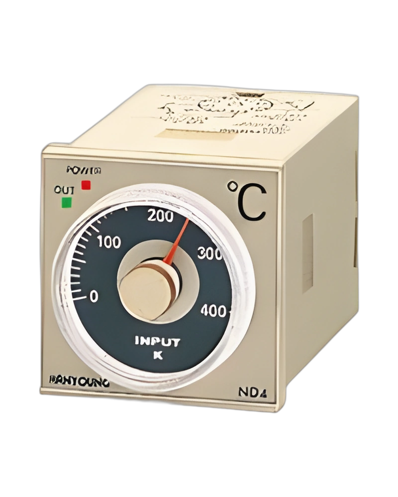
Explore performance details, construction highlights, applications, and technical information in one clear overview.
ND4 Non-indicating type is a Hanyoung NUX temperature controller for monitoring and regulating process temperature. The available configuration is built around the listed sensor inputs, control method and output arrangement, with model information of ND4 Non-indicating type. External Input Resistance: ▪Thermocouple: Max. 100 Ω ▪RTD: Max. 10 Ω per 1 wire (the resistance of each wire should be the same.); Control output: ▪Relay Output : 250 V a.c. 3 A (Resistive Load) SPDT ▪SSR Output : Voltage pulse 12 V d.c. (Resistive Load Min. 800 Ω); Control output: M | Relay; ▪Relay Output: 250 V a.c. 3 A (Resistive Load) SPDT.
For panel and process selection, the important characteristics are the input sensor type, control response, power requirements and display or communication options. Control Method: Proportional control, ON/OFF control; Setting Method: Analog setting; Weight: Approx. 220 (including installation adaptor); Dielectric strength: 2000 V a.c. 60 Hz for 1min.
Key strengths of the ND4 Non-indicating type come from the combination of its functional configuration and practical installation specifications. The following characteristics highlight the values that matter most when comparing the product with equipment requirements.
External Input Resistance: ▪Thermocouple: Max. 100 Ω ▪RTD: Max. 10 Ω per 1 wire (the resistance of each wire should be the same.); Control Method: Proportional control, ON/OFF control; Control output: ▪Relay Output : 250 V a.c. 3 A (Resistive Load) SPDT ▪SSR Output : Voltage pulse 12 V d.c. (Resistive Load Min. 800 Ω); Power supply voltage: 220 V a.c. 60 Hz; Sampling Cycle: ▪Relay Output : 20 sec ▪SSR Output : 2 sec.
The ND4 Non-indicating type is specified by its sensor input, control output, electrical supply, sampling behaviour and accuracy. These values determine how the controller measures temperature and applies its selected control response. ▪SSR Output: Voltage pulse 12 V d.c. (Resistive Load Min. 800 Ω); ▪Relay Output: 20 sec; ▪SSR Output: 2 sec; Setting Accuracy: Same as display value without relative error.
Additional technical characteristics include Sampling Cycle: ▪Relay Output : 20 sec ▪SSR Output : 2 sec; Power supply voltage: 220 V a.c. 60 Hz; Power Consumption: 3 VA.
The physical design of ND4 Non-indicating type should be considered together with the installation environment and the available mounting or display arrangement. Ambient Temperature · Humidity: 0 - 50 ℃, 35 ~ 85 % RH (Without condensation); Vibration resistance: Durability | 2 - 55 Hz, X·Y·Z in each direction for 10 min; Shock resist: Durability | 300 m/s²; External Input Resistance: ▪Thermocouple: Max. 100 Ω ▪RTD: Max. 10 Ω per 1 wire (the resistance of each wire should be the same.).
Further construction and environmental details include Control Method: Proportional control, ON/OFF control; Control output: ▪Relay Output : 250 V a.c. 3 A (Resistive Load) SPDT ▪SSR Output : Voltage pulse 12 V d.c. (Resistive Load Min. 800 Ω); Power supply voltage: 220 V a.c. 60 Hz.
Integration of ND4 Non-indicating type requires the correct sensor input, control output, supply voltage and configuration settings for the application. External Input Resistance: ▪Thermocouple: Max. 100 Ω ▪RTD: Max. 10 Ω per 1 wire (the resistance of each wire should be the same.); Control Method: Proportional control, ON/OFF control; Control output: ▪Relay Output : 250 V a.c. 3 A (Resistive Load) SPDT ▪SSR Output : Voltage pulse 12 V d.c. (Resistive Load Min. 800 Ω); Power supply voltage: 220 V a.c. 60 Hz.
Additional operating and interface details include Sampling Cycle: ▪Relay Output : 20 sec ▪SSR Output : 2 sec; Power Consumption: 3 VA; Control output: M | Relay. These values provide a practical reference for wiring, setup and normal operation within the selected configuration.
Choose ND4 Non-indicating type by confirming the exact model or configuration against the required operating conditions. The available model information is ND4 Non-indicating type. Model: Code | Content; External Input Resistance: ▪Thermocouple: Max. 100 Ω ▪RTD: Max. 10 Ω per 1 wire (the resistance of each wire should be the same.); Control Method: Proportional control, ON/OFF control; Control output: ▪Relay Output : 250 V a.c. 3 A (Resistive Load) SPDT ▪SSR Output : Voltage pulse 12 V d.c. (Resistive Load Min. 800 Ω).
Before installation, confirm Power supply voltage: 220 V a.c. 60 Hz; Sampling Cycle: ▪Relay Output : 20 sec ▪SSR Output : 2 sec; Power Consumption: 3 VA. Matching the model, electrical ratings, signal requirements, physical arrangement and environmental limits helps keep the product within its specified operating conditions.
| Specification | Details |
|---|---|
| Power supply voltage | 220 V a.c. 60 Hz |
| Voltage variation rate | ± 10 % of supply voltage |
| Power Consumption | 3 VA |
| Input | Thermocouple, RTD (Pt 100 Ω) |
| Adjusting Sensitivity | 0.2 % (fixed) of Max. Range |
| Control Method | Proportional control, ON/OFF control |
| Setting Method | Analog setting |
| Control output | ▪Relay Output : 250 V a.c. 3 A (Resistive Load) SPDT ▪SSR Output : Voltage pulse 12 V d.c. (Resistive Load Min. 800 Ω) |
| Setting Accuracy | Same as display value without relative error |
| Proportional Band | 3 % of FS (fixed) |
| Relay Life Expectancy | ▪Mechanical : Min.10 millions times. ▪Electrical : Min. 100 thousands times. (250 V a.c. 5 A Resistive Load) |
| Sampling Cycle | ▪Relay Output : 20 sec ▪SSR Output : 2 sec |
| External Input Resistance | ▪Thermocouple: Max. 100 Ω ▪RTD: Max. 10 Ω per 1 wire (the resistance of each wire should be the same.) |
| Dielectric strength | 2000 V a.c. 60 Hz for 1min |
| Ambient Temperature · Humidity | 0 - 50 ℃, 35 ~ 85 % RH (Without condensation) |
| Vibration resistance | Durability | 2 - 55 Hz, X·Y·Z in each direction for 10 min |
| Malfunction | 10 - 55 Hz, 0.76 mm, X·Y·Z in each direction for 2 min |
| Shock resist | Durability | 300 m/s² |
| Malfunction | 200 m/s² |
| Weight | Approx. 220 (including installation adaptor) |
| Model | Code | Content |
| ND4 - | Non-indicating type temperature controller |
| Control type | F | ON/OFF control (2 position control) |
| P | Proportional control |
| Input | K | K thermocouple |
| P | RTD Pt100 Ω (IEC) |
| Control output | M | Relay |
| Control operation | R | Reverse control (Heating control) |
| D | Direct control (Cooling control) |
| Range code | Select the standard range code |
| Terminal structure | T | Terminal type |
| No | Type | Category | Title | File |
| 1 | Manual > Instruction Manual | Temperature Controllers | ND4 Instruction manual |
| 1 | CAD > 2D | Temperature Controllers | ND4 (2D) |
| ▪Relay Output | 250 V a.c. 3 A (Resistive Load) SPDT |
| ▪SSR Output | Voltage pulse 12 V d.c. (Resistive Load Min. 800 Ω) |
| ▪Relay Output | 20 sec |
| ▪SSR Output | 2 sec |
Browse product families and jump into the exact catalog section you need.