
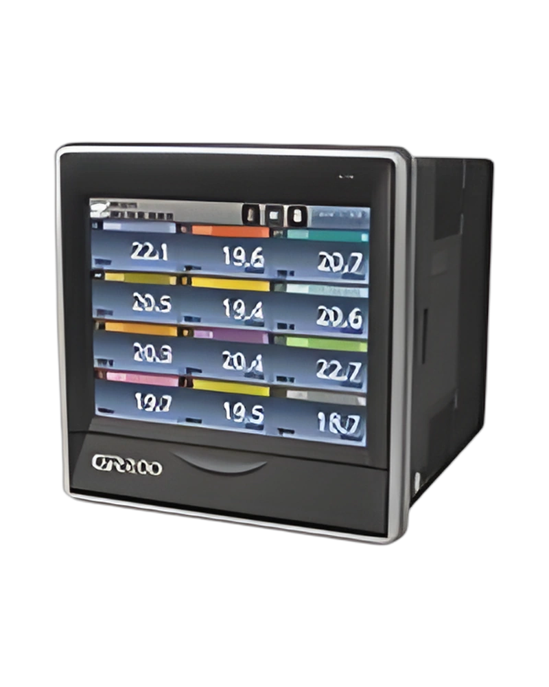
Explore performance details, construction highlights, applications, and technical information in one clear overview.
GR200A Touch panel Graphic recorder is a Hanyoung NUX recorder designed for industrial measurement, indication and process monitoring. Its configuration is determined by the available input signals, measurement or recording functions, display and output characteristics, with model information of GR200A Touch panel Graphic recorder. Input type: 2 thermoresistors (Pt-100, KPt-100) 12 thermocouples (K, J, E, T, R, B, S, L, N, U, Wre 5-26, PL-II) DC voltage 4 types (-10 - 20 mV, 0 - 100 mV, 1 - 5V, 0 - 30 V) ※ The current input (4 - 20 ㎃ d.c.) is available when you use resistance 250 Ω (0.5 W / 0.1 %) on input terminals.; Allowable input voltage: Thermocouple : Less than ±10 V d.c., VDC : Less than ±33 V d.c.; Maximum number of outputs: 12; Output type: Relay output.
The listed measurement range, accuracy, input method, display format and connection details provide the main selection points for panel and control-system integration. Display: TFT color LCD (115.2 x 86.4 ㎜, resolution : 640 x 480 pixel, LED Backlight); Language in use: Korean, English, Chinese (simplified/traditional); RS-422/485 communication: Communication speed : 9600 bps ~ 115200 bps; Ethernet communication: Communication speed : 10/100 Base-T Ethernet.
Key strengths of the GR200A Touch panel Graphic recorder come from the combination of its functional configuration and practical installation specifications. The following characteristics highlight the values that matter most when comparing the product with equipment requirements.
Input type: 2 thermoresistors (Pt-100, KPt-100) 12 thermocouples (K, J, E, T, R, B, S, L, N, U, Wre 5-26, PL-II) DC voltage 4 types (-10 - 20 mV, 0 - 100 mV, 1 - 5V, 0 - 30 V) ※ The current input (4 - 20 ㎃ d.c.) is available when you use resistance 250 Ω (0.5 W / 0.1 %) on input terminals.; Number of channels: 2, 4, 8, 12 (Refer to the type configuration); Sampling period: 250 ms; Accuracy: ±0.15 % of F.S, ±1 digit (Except the RJC temperature error) ※ Refer to the input table; Power voltage: 100 - 240 V a.c. Voltage fluctuation rate ±10 %.
The GR200A Touch panel Graphic recorder technical profile combines measurement inputs, channel capacity, sampling, accuracy, recording functions and control outputs. These parameters determine how process values can be monitored and recorded. External contact input & output (DI / DO): N | None; Sampling period: 250 ms; Accuracy: ±0.15 % of F.S, ±1 digit (Except the RJC temperature error) ※ Refer to the input table; Communication function: 1 | RS 422/485 + ETHERNET.
Additional technical characteristics include Communication speed: 9600 bps ~ 115200 bps; Communication speed: 10/100 Base-T Ethernet; Protocol: Modbus on TCP / IP.
The physical design of GR200A Touch panel Graphic recorder should be considered together with the installation environment and the available mounting or display arrangement. Weight: Approx. 1.32 kg; Ambient temperature: 0 ~ 5 ℃; Ambient humidity: 20 ~ 90 % RH (no condensation); Ambient temperature: -20 ~ 70 ℃.
Further construction and environmental details include Ambient Humidity: 5 ~ 95 % RH (However, there should be no condensation.).
Integration of GR200A Touch panel Graphic recorder begins with matching its connection, input or control signal and output requirements to the surrounding equipment. Power voltage: 100 - 240 V a.c. Voltage fluctuation rate ±10 %; Power frequency: 50 - 60 ㎐; Power consumption: 25 VA max; Input type: 2 thermoresistors (Pt-100, KPt-100) 12 thermocouples (K, J, E, T, R, B, S, L, N, U, Wre 5-26, PL-II) DC voltage 4 types (-10 - 20 mV, 0 - 100 mV, 1 - 5V, 0 - 30 V) ※ The current input (4 - 20 ㎃ d.c.) is available when you use resistance 250 Ω (0.5 W / 0.1 %) on input terminals..
Additional operating and interface details include Number of channels: 2, 4, 8, 12 (Refer to the type configuration); Sampling period: 250 ms; Accuracy: ±0.15 % of F.S, ±1 digit (Except the RJC temperature error) ※ Refer to the input table. These values provide a practical reference for wiring, setup and normal operation within the selected configuration.
Choose GR200A Touch panel Graphic recorder by confirming the exact model or configuration against the required operating conditions. The available model information is GR200A Touch panel Graphic recorder. Model: Code | Content; Input type: 2 thermoresistors (Pt-100, KPt-100) 12 thermocouples (K, J, E, T, R, B, S, L, N, U, Wre 5-26, PL-II) DC voltage 4 types (-10 - 20 mV, 0 - 100 mV, 1 - 5V, 0 - 30 V) ※ The current input (4 - 20 ㎃ d.c.) is available when you use resistance 250 Ω (0.5 W / 0.1 %) on input terminals.; Number of channels: 2, 4, 8, 12 (Refer to the type configuration); Sampling period: 250 ms.
Before installation, confirm Accuracy: ±0.15 % of F.S, ±1 digit (Except the RJC temperature error) ※ Refer to the input table; Power voltage: 100 - 240 V a.c. Voltage fluctuation rate ±10 %; Display: TFT color LCD (115.2 x 86.4 ㎜, resolution : 640 x 480 pixel, LED Backlight). Matching the model, electrical ratings, signal requirements, physical arrangement and environmental limits helps keep the product within its specified operating conditions.
| Specification | Details |
|---|---|
| Power voltage | 100 - 240 V a.c. Voltage fluctuation rate ±10 % |
| Power frequency | 50 - 60 ㎐ |
| Power consumption | 25 VA max |
| Maximum internal fuse ratings | 250 V a.c. |
| Internal voltage | Primary terminal* and secondary terminal** : Minimum 1500 V a.c. for 1 minute Primary terminal* and FG terminal : Minimum 1500 V a.c. for 1 minute Secondary terminal** and FG terminal : Minimum 1500 V a.c. for 1 minute Secondary terminal** and secondary terminal** : Minimum 500 V a.c. for 1 minute * Primary terminal : Power terminal (except the FG terminal) and the relay output terminal ** Secondary terminal : Sensor input terminal, contact input terminal, communication terminal |
| Insulation resistor | 20 MΩ between the power terminal and the FG terminal or 500 V d.c. |
| Number of channels | 2, 4, 8, 12 (Refer to the type configuration) |
| Input type | 2 thermoresistors (Pt-100, KPt-100) 12 thermocouples (K, J, E, T, R, B, S, L, N, U, Wre 5-26, PL-II) DC voltage 4 types (-10 - 20 mV, 0 - 100 mV, 1 - 5V, 0 - 30 V) ※ The current input (4 - 20 ㎃ d.c.) is available when you use resistance 250 Ω (0.5 W / 0.1 %) on input terminals. |
| Sampling period | 250 ms |
| Current to measure the thermoresistor (RTD) | About 0.21 ㎃ |
| Input resistor | Thermocouple : More than 1 MΩ, VDC : More than 1 MΩ |
| Allowable wiring resistor | Thermoresistor : Maximum 100 Ω/wire (The RTD is up to 10 Ω/wire for the range of -100.00 - .150.00) Thermocouple : Less than 200 Ω VDC : Less than 2 kΩ |
| Impact of the wiring resistor | Thermoresistor : ±0.3 °C/10 Ω (The 3 lines have the same wiring resistors) |
| Allowable input voltage | Thermocouple : Less than ±10 V d.c., VDC : Less than ±33 V d.c. |
| Accuracy | ±0.15 % of F.S, ±1 digit (Except the RJC temperature error) ※ Refer to the input table |
| RJC temperature error | ±1.5 ℃ (0 ~ 50 ℃) |
| Sensor short detection (Burn-out) | UP-Scale during disconnection |
| Maximum input | 4 |
| Input method | No voltage contact input |
| On/Off detection resistor | Consider on less than 1 kΩ minimum and off larger than 10 kΩ |
| Minimum detection time | 0.25 second |
| Maximum number of outputs | 12 |
| Output type | Relay output |
| Maximum ratings | 5 A 250 V a.c., 5 A 30 V d.c. |
| Recommended ratings | 2 A 250 V a.c., 2 A 30 V d.c. |
| Relay life | 50,000 times at the maximum ratings, 100,000 times at the recommended ratings |
| Display | TFT color LCD (115.2 x 86.4 ㎜, resolution : 640 x 480 pixel, LED Backlight) |
| Backlight life | 40,000 hours |
| Language in use | Korean, English, Chinese (simplified/traditional) |
| RS-422/485 communication | Communication speed : 9600 bps ~ 115200 bps |
| Ethernet communication | Communication speed : 10/100 Base-T Ethernet |
| Save function | Internal memory | Non-volatile memory : 350 MB - Save to 64 days in 1 second cycle (use 5.4MB per day) |
| External memory | SD card : 8GB - Store up to 512 files |
| storage cycle | user settings (1, 2, 5, 10, 20, 30, 60, 120 second) |
| memory information | Measurement value by channel, disconnection, DI (contact input), ALARM, relay output status |
| Ambient temperature | 0 ~ 5 ℃ |
| Temperature change | 10 ℃/h below |
| Ambient humidity | 20 ~ 90 % RH (no condensation) |
| Magnetic field | 400 A/m below |
| Altitude | Less than 2,000 m above the sea level |
| Weight | Approx. 1.32 kg |
| Ambient temperature | -20 ~ 70 ℃ |
| temperature change | 20 ℃/h below |
| Ambient Humidity | 5 ~ 95 % RH (However, there should be no condensation.) |
| DC voltage, thermocouple sensor | ±0.00 3% of F.S / ℃ |
| RTD sensor | ±0.03 ℃/℃ |
| Model | Code | Content |
| GR200A - | Touch Screen Graphic Recorder |
| Input channel | 2 | 2 channel |
| 4 | 4 channel |
| 8 | 8 channel |
| 12 | 12 channel |
| External contact input & output (DI / DO) | N | None |
| 1 | DI 2 contact + DO 6 contacts |
| 2 | DI 4 contact + DO 12 contacts |
| Communication function | 1 | RS 422/485 + ETHERNET |
| No | Type | Category | Title | File |
| 1 | Manual > User Manual | Recorder | GR200A User manual |
| 1 | CAD > 2D | Recorder | GR200A(2D) |
| 2 | CAD > 3D | Recorder | GR200A(3D) |
| 1 | Software > Program | ALL | Communication Protocol Examples |
| 2 | Software > Program | ALL | TCS Integrated Communication Program Installation file |
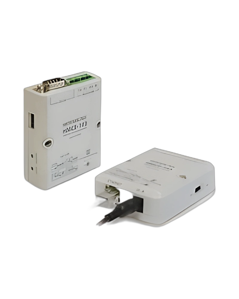
| 3 | Software > Program | Recorder | ETHERNET Converter: HMCE-103 (old) |
| 4 | Software > Program | Recorder | GR200 communication program and communication protocol (old) |
| 5 | Software > Communication data | Recorder | GR200_CommRegisterMAP_V100 (old) |
| 6 | Software > Communication data | ALL | TCS Integrated Communication Program Manual(EN) |
| 7 | Software > etc | Recorder | GR200 Date Error File Converter (old) |
| No | Mark | Category | Title | File |
| 1 | Certification > CE | Recorder | GR200A (EMC) |
| 2 | Certification > CE | Recorder | GR200A (LVD) |
| 3 | Certification > KC | Recorder | GR200A |
| Primary terminal* and secondary terminal** | Minimum 1500 V a.c. for 1 minute |
| Primary terminal* and FG terminal | Minimum 1500 V a.c. for 1 minute |
| Secondary terminal** and FG terminal | Minimum 1500 V a.c. for 1 minute |
| Secondary terminal** and secondary terminal** | Minimum 500 V a.c. for 1 minute |
| * Primary terminal | Power terminal (except the FG terminal) and the relay output terminal |
| ** Secondary terminal | Sensor input terminal, contact input terminal, communication terminal |
| VDC | Less than 2 kΩ |
| TFT color LCD (115.2 x 86.4 ㎜, resolution | 640 x 480 pixel, LED Backlight) |
| Communication speed | 9600 bps ~ 115200 bps |
| Communication speed | 10/100 Base-T Ethernet |
| IP settings | static and dynamic (DHCP) IP |
| Protocol | Modbus on TCP / IP |
| Non-volatile memory | 350 MB - Save to 64 days in 1 second cycle (use 5.4MB per day) |
Browse product families and jump into the exact catalog section you need.