
.webp)
Explore performance details, construction highlights, applications, and technical information in one clear overview.
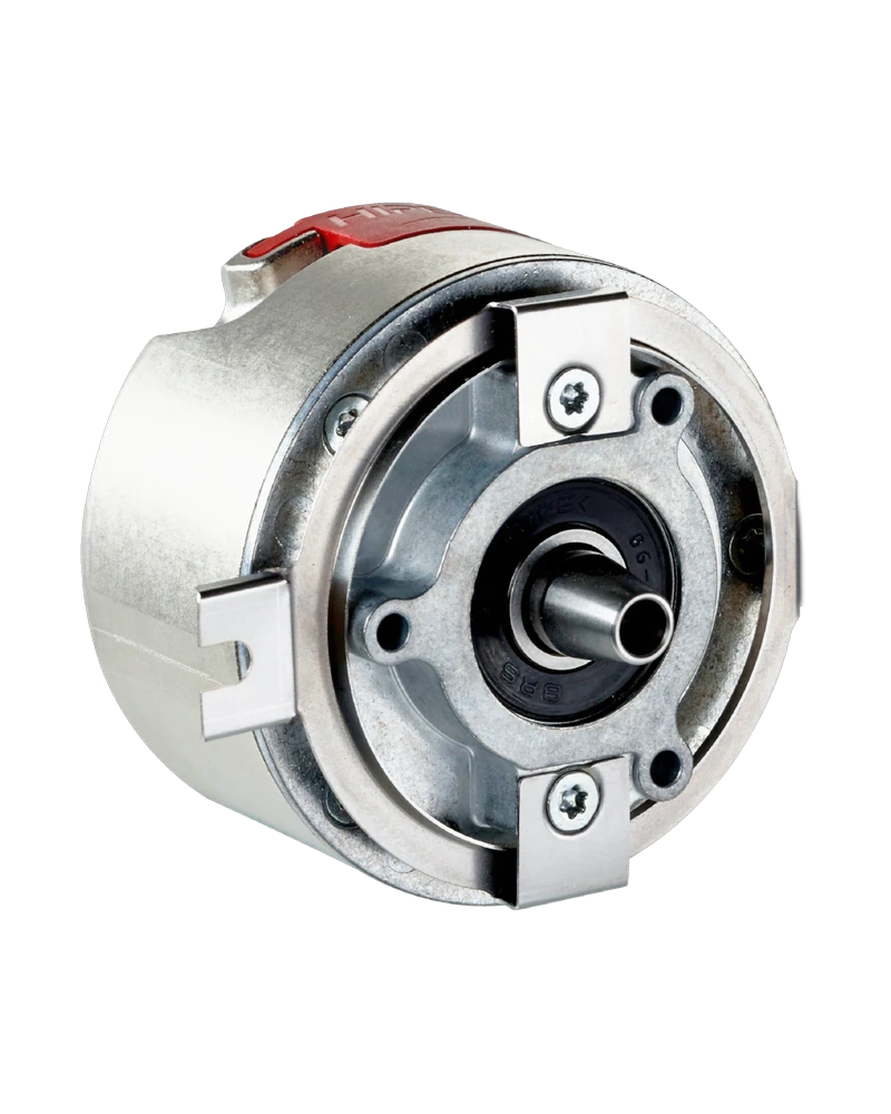
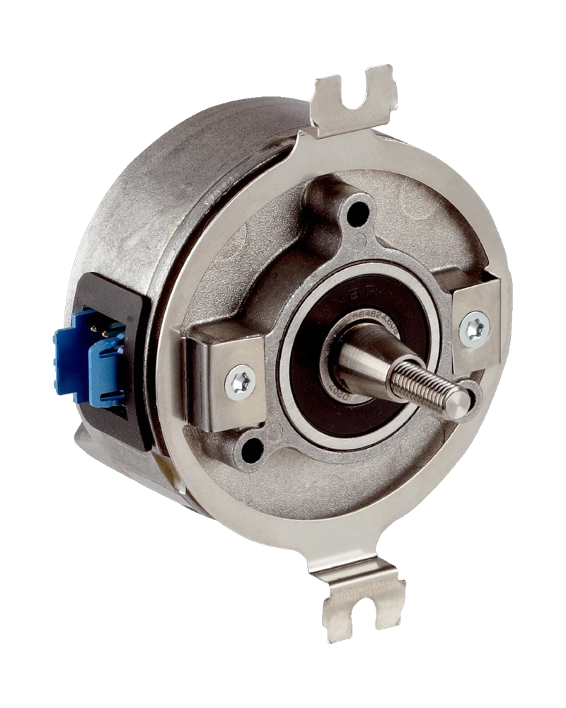
PSC series is a Hanyoung NUX rotary encoder for rotational motion and position feedback. The configuration is defined by the available model options and operating characteristics, with model information of PSC-□□- □□-N-□ | PSC-□□- □□-O-□ | PSC-□□- □□-T-□. Output type: NPN voltage output | NPN open collector | Totem Pole output; Phase difference of output: Phase difference between A and B phase : T/4 ± T/8 (1 cycle of A phase = T); Control Output: • Load Voltage: 30 V max. • Load Current: 30 ㎃ max. • Remaining voltage: 0.4 V max. | • LOW - Load Current : 30mA max. - Remaining voltage : 0.4 V max. • HIGH - Load Current : 10mA max. - Remaining voltage : Power Voltage -1.5 V min.; Response speed: 1 ㎲ max. (Wire length : 1.5 m, sinking current = 30 ㎃).
The main selection points are the product's input or load requirements, operating range, connection method, physical construction and environmental limits. Connection type: Cable extended type; Wire specification: 5 P, Ø 5.0 ㎜, Length 1.5 m (Shielded cable); Weight: Approx. 625g; Insulation resistance: 500 MΩ min. (Between all terminals and case).
Key strengths of the PSC series come from the combination of its functional configuration and practical installation specifications. The following characteristics highlight the values that matter most when comparing the product with equipment requirements.
Output type: NPN voltage output | NPN open collector | Totem Pole output; Phase difference of output: Phase difference between A and B phase : T/4 ± T/8 (1 cycle of A phase = T); Max. response: 100 K㎐; Power voltage: 5 - 12 V d.c. (±5 %), 12 - 24 V d.c. (±5 %); Response speed: 1 ㎲ max. (Wire length : 1.5 m, sinking current = 30 ㎃).
The main technical characteristics of PSC series are defined by its electrical ratings, operating inputs or outputs, performance values and control or indication functions. These specifications provide the working limits for the selected configuration. Power voltage: 5 - 12 V d.c. (±5 %), 12 - 24 V d.c. (±5 %); • Load Voltage: 30 V max.; Max. response: 100 K㎐; Dielectric strength: 500 V a.c. (Between all terminals and case for 1 minute at 50 Hz).
Additional technical characteristics include Vibration resistance: 10 - 55 ㎐ (for 1 minute cycle), double amplitude width : 1.5 ㎜, in each direction of X · Y · Z for 2 hours; Shock resistance: 735 m/s² max.; Ambient temperature: -10 ~ 70 ℃ (Without freezing), Storage : -25 ~ 85 ℃.
The physical design of PSC series should be considered together with the installation environment and the available mounting or display arrangement. Ambient humidity: 35 ~ 85 % R.H.; Output type: NPN voltage output | NPN open collector | Totem Pole output; Phase difference of output: Phase difference between A and B phase : T/4 ± T/8 (1 cycle of A phase = T); Max. response: 100 K㎐.
Further construction and environmental details include Power voltage: 5 - 12 V d.c. (±5 %), 12 - 24 V d.c. (±5 %); Response speed: 1 ㎲ max. (Wire length : 1.5 m, sinking current = 30 ㎃); Control Output: • Load Voltage: 30 V max. • Load Current: 30 ㎃ max. • Remaining voltage: 0.4 V max. | • LOW - Load Current : 30mA max. - Remaining voltage : 0.4 V max. • HIGH - Load Current : 10mA max. - Remaining voltage : Power Voltage -1.5 V min..
Integration of PSC series begins with matching its connection, input or control signal and output requirements to the surrounding equipment. Output type: NPN voltage output | NPN open collector | Totem Pole output; Phase difference of output: Phase difference between A and B phase : T/4 ± T/8 (1 cycle of A phase = T); Max. response: 100 K㎐; Power voltage: 5 - 12 V d.c. (±5 %), 12 - 24 V d.c. (±5 %).
Additional operating and interface details include Response speed: 1 ㎲ max. (Wire length : 1.5 m, sinking current = 30 ㎃); Control Output: • Load Voltage: 30 V max. • Load Current: 30 ㎃ max. • Remaining voltage: 0.4 V max. | • LOW - Load Current : 30mA max. - Remaining voltage : 0.4 V max. • HIGH - Load Current : 10mA max. - Remaining voltage : Power Voltage -1.5 V min.; Wire specification: 5 P, Ø 5.0 ㎜, Length 1.5 m (Shielded cable). These values provide a practical reference for wiring, setup and normal operation within the selected configuration.
Choose PSC series by confirming the exact model or configuration against the required operating conditions. The available model information is PSC-□□- □□-N-□ | PSC-□□- □□-O-□ | PSC-□□- □□-T-□. Model: PSC-□□- □□-N-□ | PSC-□□- □□-O-□ | PSC-□□- □□-T-□; Output type: NPN voltage output | NPN open collector | Totem Pole output; Phase difference of output: Phase difference between A and B phase : T/4 ± T/8 (1 cycle of A phase = T); Max. response: 100 K㎐.
Before installation, confirm Power voltage: 5 - 12 V d.c. (±5 %), 12 - 24 V d.c. (±5 %); Response speed: 1 ㎲ max. (Wire length : 1.5 m, sinking current = 30 ㎃); Control Output: • Load Voltage: 30 V max. • Load Current: 30 ㎃ max. • Remaining voltage: 0.4 V max. | • LOW - Load Current : 30mA max. - Remaining voltage : 0.4 V max. • HIGH - Load Current : 10mA max. - Remaining voltage : Power Voltage -1.5 V min.. Matching the model, electrical ratings, signal requirements, physical arrangement and environmental limits helps keep the product within its specified operating conditions.
| Specification | Details |
|---|---|
| Model | PSC-□□- □□-N-□ | PSC-□□- □□-O-□ | PSC-□□- □□-T-□ |
| Output type | NPN voltage output | NPN open collector | Totem Pole output |
| Electrical specifi cation | Output phase | A, B phase output (PSC-MA, YA), Rests are A,B,Z phase output |
| Phase difference of output | Phase difference between A and B phase : T/4 ± T/8 (1 cycle of A phase = T) |
| Max. response | 100 K㎐ |
| Power voltage | 5 - 12 V d.c. (±5 %), 12 - 24 V d.c. (±5 %) |
| Power Consump tion | 60 ㎃ max. |
| Connection type | Cable extended type |
| Control Output | • Load Voltage: 30 V max. • Load Current: 30 ㎃ max. • Remaining voltage: 0.4 V max. | • LOW - Load Current : 30mA max. - Remaining voltage : 0.4 V max. • HIGH - Load Current : 10mA max. - Remaining voltage : Power Voltage -1.5 V min. |
| Response speed | 1 ㎲ max. (Wire length : 1.5 m, sinking current = 30 ㎃) |
| Mechanical specifi cation | Starting torque | 200 gf·㎝ (19.600 u N·m) max. |
| Shaft inertial moment | 5,000 r/min |
| Insulation resistance | 500 MΩ min. (Between all terminals and case) |
| Dielectric strength | 500 V a.c. (Between all terminals and case for 1 minute at 50 Hz) |
| Vibration resistance | 10 - 55 ㎐ (for 1 minute cycle), double amplitude width : 1.5 ㎜, in each direction of X · Y · Z for 2 hours |
| Shock resistance | 735 m/s² max. |
| Ambient temperature | -10 ~ 70 ℃ (Without freezing), Storage : -25 ~ 85 ℃ |
| Ambient humidity | 35 ~ 85 % R.H. |
| Wire specification | 5 P, Ø 5.0 ㎜, Length 1.5 m (Shielded cable) |
| Weight | Approx. 625g |
| No | Type | Category | Title | File |
| 1 | Manual > Instruction Manual | Rotary Encoder | PSC Manual |
| 2 | Manual > Catalogue | Rotary Encoder | PSC Catalogue |
| 1 | CAD > 2D | Rotary Encoder | PSC (2D) |
| No | Mark | Category | Title | File |
| 1 | Certification > CE | Rotary Encoder | HE series(HE40B, HE40HB, HE50B & PSC) _ EMC |
| Phase difference between A and B phase | T/4 ± T/8 (1 cycle of A phase = T) |
| • Load Voltage | 30 V max. |
| • Load Current | 30 ㎃ max. |
| • Remaining voltage | 0.4 V max. |
| - Load Current | 30mA max. |
| - Remaining voltage | 0.4 V max. |
| - Load Current | 10mA max. |
| - Remaining voltage | Power Voltage -1.5 V min. |
| 1 ㎲ max. (Wire length | 1.5 m, sinking current = 30 ㎃) |
Browse product families and jump into the exact catalog section you need.