
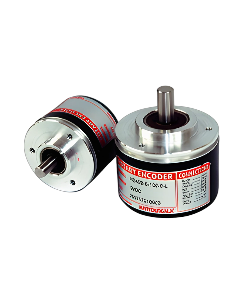
Explore performance details, construction highlights, applications, and technical information in one clear overview.
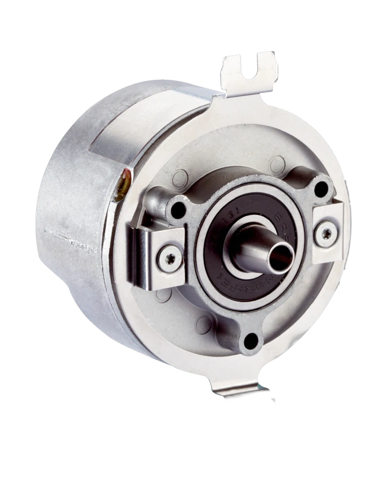
HE50B -8-500-6-L-5 is a Hanyoung NUX rotary encoder for rotational motion and position feedback. The configuration is defined by the available model options and operating characteristics, with model information of HE□□B -□-□-N-□ | HE□□B -□-□-O-□ | HE□□B -□-□-T-□ | HE□□B -□-□-L-□. Output type: NPN Voltage output | NPN Open collector output | Totem Pole output | Line Drive output; output signal: A, B, Z phase | A, B, Z, /A, /B, /Z phase; Phase difference on Output: Phase difference between A, B phase : T/4 ± T/8 (Cycle of A phase = T); Control output: Load voltage : 30 V Max. Load Current : 30 mA Max. Residual Voltage : 0.4 V Max. | * For Low Load Current: 30 mA Max. Remaining Voltage: 0.4 V Max. * For High Load Current: 10 mA Max. Remaining Voltage: Power Voltage: -2.5 V min. | * For Low Load Current: 20 mA Max. Remaining Voltage: 0.4 V Max. * For High Load Current: 20 mA Max. Remaining Voltage: 2.5 V min..
The main selection points are the product's input or load requirements, operating range, connection method, physical construction and environmental limits. Connection method: Cable extended type; Weight: Ø40 : 170g Ø50 : 200g; Insulation Resistance: Over 100 ㏁ (Base on 500 V d.c mega between terminal and case); Dielectric strength: 800 V a.c (Between terminal and case at 60 ㎐ for 1 minute).
Key strengths of the HE50B -8-500-6-L-5 come from the combination of its functional configuration and practical installation specifications. The following characteristics highlight the values that matter most when comparing the product with equipment requirements.
Output type: NPN Voltage output | NPN Open collector output | Totem Pole output | Line Drive output; Max Response Frequency: 300 ㎑; Power voltage: 5 - 12 V d.c /12 - 24 V d.c. ±5 % | 5/12/24 V d.c. ±5 %; Control output: Load voltage : 30 V Max. Load Current : 30 mA Max. Residual Voltage : 0.4 V Max. | * For Low Load Current: 30 mA Max. Remaining Voltage: 0.4 V Max. * For High Load Current: 10 mA Max. Remaining Voltage: Power Voltage: -2.5 V min. | * For Low Load Current: 20 mA Max. Remaining Voltage: 0.4 V Max. * For High Load Current: 20 mA Max. Remaining Voltage: 2.5 V min.; Starting Torque: Ø40: 4 x 10 -3 N·m max. Ø50: 7 x 10 -3 N·m max..
The main technical characteristics of HE50B -8-500-6-L-5 are defined by its electrical ratings, operating inputs or outputs, performance values and control or indication functions. These specifications provide the working limits for the selected configuration. Response Time: 1 ㎲ Max. (Cable length 1.5 m / sink=30 mA) | 1 ㎲ Max. (Cable length 1.5 m / sink=10 mA) | 1 ㎲ Max. (Cable length 1.5 m / sink=30 mA); Max Response Frequency: 300 ㎑; Power voltage: 5 - 12 V d.c /12 - 24 V d.c. ±5 % | 5/12/24 V d.c. ±5 %; Current Consumption: 60mA Max. (No-load).
Additional technical characteristics include Load voltage: 30 V Max.; Power Voltage: -2.5 V min.; Vibration Resistance: 10 -55 ㎐ (Cycle for 1 minute), Double amplitude width : 1.5 mm, each X · Y · Z direction for 2 hours.
The physical design of HE50B -8-500-6-L-5 should be considered together with the installation environment and the available mounting or display arrangement. Shock Resistance: Ø40 : 490 m/s² Max. Ø50 : 735 m/s² Max.; Ambient Temperature: -10 ~ 70 ˚C (Without condensation), Storage Temperature : -25 ~ 85 ˚C; Ambient Humidity: 35 ~ 85 % R.H; -10 ~ 70 ˚C (Without condensation), Storage Temperature: -25 ~ 85 ˚C.
Further construction and environmental details include .
Integration of HE50B -8-500-6-L-5 begins with matching its connection, input or control signal and output requirements to the surrounding equipment. Output type: NPN Voltage output | NPN Open collector output | Totem Pole output | Line Drive output; Max Response Frequency: 300 ㎑; Power voltage: 5 - 12 V d.c /12 - 24 V d.c. ±5 % | 5/12/24 V d.c. ±5 %; Control output: Load voltage : 30 V Max. Load Current : 30 mA Max. Residual Voltage : 0.4 V Max. | * For Low Load Current: 30 mA Max. Remaining Voltage: 0.4 V Max. * For High Load Current: 10 mA Max. Remaining Voltage: Power Voltage: -2.5 V min. | * For Low Load Current: 20 mA Max. Remaining Voltage: 0.4 V Max. * For High Load Current: 20 mA Max. Remaining Voltage: 2.5 V min..
Additional operating and interface details include Starting Torque: Ø40: 4 x 10 -3 N·m max. Ø50: 7 x 10 -3 N·m max.; Weight: Ø40 : 170g Ø50 : 200g; Ambient Temperature: -10 ~ 70 ˚C (Without condensation), Storage Temperature : -25 ~ 85 ˚C. These values provide a practical reference for wiring, setup and normal operation within the selected configuration.
Choose HE50B -8-500-6-L-5 by confirming the exact model or configuration against the required operating conditions. The available model information is HE□□B -□-□-N-□ | HE□□B -□-□-O-□ | HE□□B -□-□-T-□ | HE□□B -□-□-L-□. Model: HE□□B -□-□-N-□ | HE□□B -□-□-O-□ | HE□□B -□-□-T-□ | HE□□B -□-□-L-□; Output type: NPN Voltage output | NPN Open collector output | Totem Pole output | Line Drive output; Max Response Frequency: 300 ㎑; Power voltage: 5 - 12 V d.c /12 - 24 V d.c. ±5 % | 5/12/24 V d.c. ±5 %.
Before installation, confirm Control output: Load voltage : 30 V Max. Load Current : 30 mA Max. Residual Voltage : 0.4 V Max. | * For Low Load Current: 30 mA Max. Remaining Voltage: 0.4 V Max. * For High Load Current: 10 mA Max. Remaining Voltage: Power Voltage: -2.5 V min. | * For Low Load Current: 20 mA Max. Remaining Voltage: 0.4 V Max. * For High Load Current: 20 mA Max. Remaining Voltage: 2.5 V min.; Starting Torque: Ø40: 4 x 10 -3 N·m max. Ø50: 7 x 10 -3 N·m max.; Weight: Ø40 : 170g Ø50 : 200g. Matching the model, electrical ratings, signal requirements, physical arrangement and environmental limits helps keep the product within its specified operating conditions.
| Specification | Details |
|---|---|
| Model | HE□□B -□-□-N-□ | HE□□B -□-□-O-□ | HE□□B -□-□-T-□ | HE□□B -□-□-L-□ |
| Output type | NPN Voltage output | NPN Open collector output | Totem Pole output | Line Drive output |
| Insulation Resistance | Over 100 ㏁ (Base on 500 V d.c mega between terminal and case) |
| Dielectric strength | 800 V a.c (Between terminal and case at 60 ㎐ for 1 minute) |
| Vibration Resistance | 10 -55 ㎐ (Cycle for 1 minute), Double amplitude width : 1.5 mm, each X · Y · Z direction for 2 hours |
| Shock Resistance | Ø40 : 490 m/s² Max. Ø50 : 735 m/s² Max. |
| Ambient Temperature | -10 ~ 70 ˚C (Without condensation), Storage Temperature : -25 ~ 85 ˚C |
| Ambient Humidity | 35 ~ 85 % R.H |
| Protection | Protection IP 50 (IEC Standard) |
| Wire Specifi cation | 5P, Ø5.0㎜, Length : 1.5 m, Shield cable (Option : 2 m, 8 m, 10 m) (Line Driver Type : 8P, Ø 5.0 ㎜, Length : 1.5m, Shield cable) |
| Weight | Ø40 : 170g Ø50 : 200g |
| Accessory | Ø40 : Ø6.0 or Ø8.0 mm Coupling, Ø50 : Ø8.0 mm Coupling, Bracket |
| output signal | A, B, Z phase | A, B, Z, /A, /B, /Z phase |
| Phase difference on Output | Phase difference between A, B phase : T/4 ± T/8 (Cycle of A phase = T) |
| Max Response Frequency | 300 ㎑ |
| Power voltage | 5 - 12 V d.c /12 - 24 V d.c. ±5 % | 5/12/24 V d.c. ±5 % |
| Current Consumption | 60mA Max. (No-load) |
| Connection method | Cable extended type |
| Control output | Load voltage : 30 V Max. Load Current : 30 mA Max. Residual Voltage : 0.4 V Max. | * For Low Load Current: 30 mA Max. Remaining Voltage: 0.4 V Max. * For High Load Current: 10 mA Max. Remaining Voltage: Power Voltage: -2.5 V min. | * For Low Load Current: 20 mA Max. Remaining Voltage: 0.4 V Max. * For High Load Current: 20 mA Max. Remaining Voltage: 2.5 V min. |
| Response Time | 1 ㎲ Max. (Cable length 1.5 m / sink=30 mA) | 1 ㎲ Max. (Cable length 1.5 m / sink=10 mA) | 1 ㎲ Max. (Cable length 1.5 m / sink=30 mA) |
| Starting Torque | Ø40: 4 x 10 -3 N·m max. Ø50: 7 x 10 -3 N·m max. |
| Moment of inertia | Ø40 : 4 X 10 -6 kg · ㎡ max Ø50 : 7 x 10 -6 kg · ㎡ max |
| Permissible Shaft Loading | Ø40 : Radial : Within 30 N , Thrust : Within 20 N Ø50 : Radial : Within 50 N , Thrust : Within 30 N |
| Max. Permissible Revolution | 5000 r/min |
| No | Type | Category | Title | File |
| 1 | Manual > Instruction Manual | Rotary Encoder | HE40B/HE50B manual |
| 1 | CAD > 2D | Rotary Encoder | HE40_50_68 series (2D) |
| 2 | CAD > 3D | Rotary Encoder | HE40B/HE50B (3D) |
| No | Mark | Category | Title | File |
| 1 | Certification > CE | Rotary Encoder | HE series(HE40B, HE40HB, HE50B & PSC) _ EMC |
| -10 ~ 70 ˚C (Without condensation), Storage Temperature | -25 ~ 85 ˚C |
| Phase difference between A, B phase | T/4 ± T/8 (Cycle of A phase = T) |
| Load voltage | 30 V Max. |
| Load Current | 30 mA Max. |
| Residual Voltage | 0.4 V Max. |
| Remaining Voltage | 0.4 V Max. |
| Load Current | 10 mA Max. |
| Power Voltage | -2.5 V min. |
| Load Current | 20 mA Max. |
| Remaining Voltage | 2.5 V min. |
Browse product families and jump into the exact catalog section you need.