
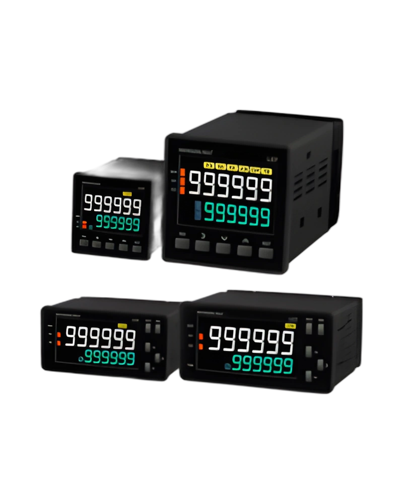
Explore performance details, construction highlights, applications, and technical information in one clear overview.
LC series is a Hanyoung NUX counter / timer for counting events and controlling time-based operations. Its model configuration determines the input method, timing or counting range, display and output functions, with model information of LC1 | LC3 | LC4. Minimum input signal time: 1 ms / 20 ms (START, INHIBIT, RESET inputs); response waiting time: 5 ~ 99 ms; Character height: Counting unit (10.2 mm) Setting unit (3.5 mm) | Counting unit (14.5 mm) Setting unit (10 mm) | ▪6 Digit Counting unit (10.8 mm) Setting unit (8 mm) ▪4 Digit Counting unit (14 mm) Setting unit (8.5 mm); Character height: Counting unit (10.5 mm) Setting unit (6.7 mm) | Counting unit (17.2 mm) Setting unit (12.5 mm).
The operating range, signal conditions, display format, computation speed and connection method should be checked against the machine sequence before installation. Display digits: 4 | 4 digits (9999) ※LC1/LC4 only; Weight: 78 g | 196 g | 140 g; Weight: 143 g | 222 g; Dimensions: 1 | 48(W) x 24(H) mm.
Key strengths of the LC series come from the combination of its functional configuration and practical installation specifications. The following characteristics highlight the values that matter most when comparing the product with equipment requirements.
Power voltage: AC | 100 - 240 V a.c. 50/60 Hz (Voltage fluctuation rate: ±10%); Display digits: 4 | 4 digits (9999) ※LC1/LC4 only; Control output: Contact output | 1- stage | OUT (SPST, 1a) | OUT (SPDT, 1c); Minimum input signal time: 1 ms / 20 ms (START, INHIBIT, RESET inputs); response waiting time: 5 ~ 99 ms.
The LC series technical characteristics define the supported input conditions, counting or timing range, display resolution, computation speed and output behaviour. These values determine how the unit responds to machine signals. Power voltage: AC | 100 - 240 V a.c. 50/60 Hz (Voltage fluctuation rate: ±10%); Power consumption: AC | 1-stage setting type: max. 7.4 VA | ▪2-stage setting type : max. 12 VA ▪1-stage setting type : max. 11 VA; Power voltage: AC | 100 - 240 V a.c. 50/60 Hz (Voltage fluctuation rate : ±10%); Power consumption: AC | ▪2-stage setting type : max. 12 VA ▪1-stage setting type : max. 11 VA.
Additional technical characteristics include External power supply: 12 V d.c. 100 mA max; Power voltage: A | 100 - 240 V a.c. 50/60 Hz; 100 - 240 V a.c. 50/60 Hz (Voltage fluctuation rate: ±10%).
The physical design of LC series should be considered together with the installation environment and the available mounting or display arrangement. Product dimensions (Includes protective cover): W | 48.0 | 96.0 | 48.0 | 72.0 | 72.0; Panel cutout: W1 | 45.0 | 91.0 | 45.0 | 66.5 | 68.0; Insulation resistance: Min. 100 MΩ (500 V d.c.) conductive part terminal - unfilled metal; Dielectric strength: 2000 V a.c. 60 Hz for 1 minute (different live part terminals).
Further construction and environmental details include Noise immunity: Square-wave noise by noise simulator ±2000 V (pulse width 1 ㎲); Shock resistance: 300 m/s² (30G), 3 times each in X, Y and Z direction; Vibration durability: 10 - 55 Hz, single amplitude 0.5 mm, 3-axis each direction, 2 h.
Integration of LC series begins with matching its connection, input or control signal and output requirements to the surrounding equipment. Control output: Contact output | 1- stage | OUT (SPST, 1a) | OUT (SPDT, 1c); Contact less output: 1- stage | NPN 1 circuits (OUT) | NPN 2 circuits (OUT, BAT.O) ※LC4-P61C/P41C models NPN 1-circuit configuration; Contact less output: 1- stage | NPN 2 circuits (OUT, BAT.O) ※LC6-P61C models NPN 1-circuit configuration; ONE SHOT output: 0.01 ~ 99.99 sec.
Additional operating and interface details include Control output: 1 | 1-stage output; Sub output: N | No sub output; 24 - 48 V a.c. 50/60 Hz or 24 - 48 V d.c. (Voltage fluctuation rate: ±10%). These values provide a practical reference for wiring, setup and normal operation within the selected configuration.
Choose LC series by confirming the exact model or configuration against the required operating conditions. The available model information is LC1 | LC3 | LC4. Model: LC1 | LC3 | LC4; Model: LC6 | LC7; Model: Code | Content; Degree of protection: IP66 (product front).
Before installation, confirm Storage temperature: -25 ~ 65 ℃ (without condensation); Ambient temperature & humidity: -10 ~ 55 ℃, 35 ~ 85% RH (without condensation). Matching the model, electrical ratings, signal requirements, physical arrangement and environmental limits helps keep the product within its specified operating conditions.
| Specification | Details |
|---|---|
| Model | LC1 | LC3 | LC4 |
| Power voltage | AC | 100 - 240 V a.c. 50/60 Hz (Voltage fluctuation rate: ±10%) |
| DC | - | 24 - 48 V a.c. 50/60 Hz or 24 - 48 V d.c. (Voltage fluctuation rate: ±10%) |
| Power consumption | AC | 1-stage setting type: max. 7.4 VA | ▪2-stage setting type : max. 12 VA ▪1-stage setting type : max. 11 VA |
| DC | - | ▪2-stage setting type : max. 6 W ▪1-stage setting type : max. 5 W |
| Character height | Counting unit (10.2 mm) Setting unit (3.5 mm) | Counting unit (14.5 mm) Setting unit (10 mm) | ▪6 Digit Counting unit (10.8 mm) Setting unit (8 mm) ▪4 Digit Counting unit (14 mm) Setting unit (8.5 mm) |
| Control output | Contact output | 1- stage | OUT (SPST, 1a) | OUT (SPDT, 1c) |
| 2- stage | - | OUT1 (SPST, 1a), OUT2 (SPDT, 1c) |
| Capacity | 250 V a.c. 5 A, resistive load | ▪SPDT: NC (250 V a.c. 2 A), NO (250 V a.c. 5 A), resistive load ▪SPST: 250 V a.c. 5 A, resistive load |
| Contact less output | 1- stage | NPN 1 circuits (OUT) | NPN 2 circuits (OUT, BAT.O) ※LC4-P61C/P41C models NPN 1-circuit configuration |
| 2- stage | - | NPN 2 circuits (OUT1, OUT2) | - |
| Capacity | Open collector, max. 30 V d.c. 100 mA |
| Weight | 78 g | 196 g | 140 g |
| Model | LC6 | LC7 |
| Power voltage | AC | 100 - 240 V a.c. 50/60 Hz (Voltage fluctuation rate : ±10%) |
| DC | 24 - 48 V a.c. 50/60 Hz or 24 - 48 V d.c. (Voltage fluctuation rate : ±10%) |
| Power consumption | AC | ▪2-stage setting type : max. 12 VA ▪1-stage setting type : max. 11 VA |
| DC | ▪2-stage setting type : max. 6 W ▪1-stage setting type : max. 5 W |
| Character height | Counting unit (10.5 mm) Setting unit (6.7 mm) | Counting unit (17.2 mm) Setting unit (12.5 mm) |
| 2- stage | OUT1 (SPST, 1a), OUT2 (SPDT, 1c) ※OUT2 of LC6-P62C: SPST configuration |
| Capacity | ▪SPDT: NC (250 V a.c. 2 A), NO (250 V a.c. 5 A), resistive load ▪SPST: 250 V a.c. 5 A, resistive load |
| Contact less output | 1- stage | NPN 2 circuits (OUT, BAT.O) ※LC6-P61C models NPN 1-circuit configuration |
| 2- stage | - | NPN 2 circuits (OUT1, OUT2) |
| Weight | 143 g | 222 g |
| Maximum counting speed | 1 cps / 30 cps / 1 kcps / 10 kcps |
| Power outage compensation | 10 years (using non-volatile memory) |
| Input | ▪Selection of input method by external switch (voltage input / non-voltage input) ▪Counter: composed of CP1, CP2, RESET, BATCH -RESET ▪Timer: composed of START, INHIBIT, RESET ▪Voltage input: HIGH level (5 - 30 V d.c.), LOW level (0 - 2 V d.c.), input resistance (about 4.5 KΩ) ▪Non-voltage input: impedance during short-circuit (max. 1 KΩ), residual voltage during short-circuit (max. 2 V d.c.) |
| Minimum input signal time | 1 ms / 20 ms (START, INHIBIT, RESET inputs) |
| External power supply | 12 V d.c. 100 mA max |
| ONE SHOT output | 0.01 ~ 99.99 sec |
| Timer operation error | ▪Power start : max. ±0.01 % ±0.05 sec ▪Reset start : max. ±0.01 % ±0.03 sec |
| Com muni cation | protocol | Modbus RTU |
| method | RS485 (2-wire half-duplex) |
| syn chronism | Asynchronous |
| speed | 2,400 / 4,800 / 9,600 / 19,200 / 38,400 bps |
| effective distance | Max. within 800 m |
| max. connec tions | 31 (address : 1 ~ 127) |
| response waiting time | 5 ~ 99 ms |
| START BIT | 1 bit (fixed) |
| STOP BIT | 1 bit (fixed) |
| DATA BIT | 8 bit |
| PARITY BIT | None / Odd / Even |
| Insulation resistance | Min. 100 MΩ (500 V d.c.) conductive part terminal - unfilled metal |
| Dielectric strength | 2000 V a.c. 60 Hz for 1 minute (different live part terminals) |
| Noise immunity | Square-wave noise by noise simulator ±2000 V (pulse width 1 ㎲) |
| Shock resistance | 300 m/s² (30G), 3 times each in X, Y and Z direction |
| Vibration durability | 10 - 55 Hz, single amplitude 0.5 mm, 3-axis each direction, 2 h |
| Relay life | elec trical | Min. 50,000 times |
| mecha nical | Min. 10,000,000 times |
| Degree of protection | IP66 (product front) |
| Storage temperature | -25 ~ 65 ℃ (without condensation) |
| Ambient temperature & humidity | -10 ~ 55 ℃, 35 ~ 85% RH (without condensation) |
| Model | Code | Content |
| LC | - | LCD Counter / Timer |
| Dimensions | 1 | 48(W) x 24(H) mm |
| 3 | 96(W) x 48(H) mm |
| 4 | 48(W) x 48(H) mm |
| 6 | 72(W) x 36(H) mm |
| 7 | 72(W) X 72(H) mm |
| Settings | P | Preset Counter / Timer |
| Display digits | 4 | 4 digits (9999) ※LC1/LC4 only |
| 6 | 6 digits (999999) |
| Control output | 1 | 1-stage output |
| 2 | 2-stage output ※LC1 except |
| Sub output | N | No sub output |
| C | RS485 (MODBUS-RTU) |
| Power voltage | A | 100 - 240 V a.c. 50/60 Hz |
| D | 24 - 48 V a.c. 50/60 Hz or 24 - 48 V d.c. ※LC1 except |
| Classi fication | Type | LC1 | LC3 | LC4 | LC6 | LC7 |
| Product dimensions (Includes protective cover) | W | 48.0 | 96.0 | 48.0 | 72.0 | 72.0 |
| H | 24.0 | 48.0 | 48.0 | 36.0 | 72.0 |
| D | 75.0 | 53.0 | 64.3 | 66.0 | 73.5 |
| D1 | 4.0 | 3.8 | 3.5 | 3.5 | 3.8 |
| D2 | 15.0 | 18.1 | 16.7 | 18.1 | 20.6 |
| L | 90.0 | 71.1 | 81.0 | 84.1 | 94.1 |
| H2 | 24.0 | 44.8 | 44.8 | 30.5 | 67.0 |
| Panel cutout | W1 | 45.0 | 91.0 | 45.0 | 66.5 | 68.0 |
| H1 | 22.4 | 45.0 | 45.0 | 32.0 | 68.0 |
| A | 65.0 | 121.0 | 60.0 | 96.5 | 82.0 |
| B | 41.0 | 70.0 | 60.0 | 57.0 | 82.0 |
| No | Type | Category | Title | File |
| 1 | Manual > Instruction Manual | Counter / Timer | LC series User manual |
| 2 | Manual > Instruction Manual | Counter / Timer | LC series Instruction manual |
| 1 | CAD > 2D | Counter / Timer | LC series (2D) |
| 2 | CAD > 3D | Counter / Timer | LC series (3D) |
| 1 | Software > Program | ALL | Communication Protocol Examples |
| 2 | Software > Program | ALL | TCS Integrated Communication Program Installation file |
| 3 | Software > Communication data | ALL | TCS Integrated Communication Program Manual(EN) |
| No | Mark | Category | Title | File |
| 1 | Certification > CE | Counter / Timer | LC1-P EMC (DoC) |
| 2 | Certification > CE | Counter / Timer | LC1-P LVD (DoC) |
| 3 | Certification > CE | Counter / Timer | LC3, LC4, LC6, LC7 (EMC) |
| 4 | Certification > CE | Counter / Timer | LC3, LC4, LC6, LC7 (LVD) |
| 5 | Certification > KC | Counter / Timer | LC1-P |
| 6 | Certification > KC | Counter / Timer | LC3, LC4, LC6, LC7 |
| 100 - 240 V a.c. 50/60 Hz (Voltage fluctuation rate | ±10%) |
| 24 - 48 V a.c. 50/60 Hz or 24 - 48 V d.c. (Voltage fluctuation rate | ±10%) |
| ▪2-stage setting type | max. 12 VA ▪1-stage setting type : max. 11 VA |
| ▪2-stage setting type | max. 6 W ▪1-stage setting type : max. 5 W |
| ▪Counter | composed of CP1, CP2, RESET, BATCH -RESET |
| ▪Voltage input | HIGH level (5 - 30 V d.c.), LOW level (0 - 2 V d.c.), input resistance (about 4.5 KΩ) |
| ▪Non-voltage input | impedance during short-circuit (max. 1 KΩ), residual voltage during short-circuit (max. 2 V d.c.) |
| ▪Power start | max. ±0.01 % ±0.05 sec |
Browse product families and jump into the exact catalog section you need.